|
CMS Pixel Detector
Miscellaneous
|
|
Phase 1
Phase 2
|
|
Layer 1 Replacement
Layers 2-4
|
| Layer 1 Replacement Elog |
Not logged in |
 |
|
|
|
Message ID: 38
Entry time: Thu Nov 28 15:58:20 2019
|
| Author: |
Matej Roguljic |
| Category: |
General |
| Subject: |
Activities 26.-29.11.2019. |
|
|
26.11.
Prepared the tools for RD53A digital module assembly in the assembly lab
Investigated if the latest pXar commit solved the issue with PhOptimization, now called Ph, and it runs successfully.
Investigated the bump bonding issue in which pXar reports bad bumps, but we suspected that was not the case. And indeed, putting a source on top of the chip reported to have bad bumps and taking data shows that there are no bad bumps as reported by pXar. Our conclusion was that the BB test developed by PSI is not applicable for bumps bonded by Helsinki. BB2 seems to be appropriate.
27.11.
Assembled a Phase 2 digital module using good ROCs - 1A48, 1A47, 1A43, 1A42; being ROC 0,1,2 and 3, respectively.
Used X-ray box to confirm our BB findings yesterday and the results agree that there are no defective bumps (as reported by pXar) on M1534.
28.11.
Took a look at the assembled module and it seems that one corner of the HDI was not properly glued. There are also solder marks on a couple of pads so we decided not to wire-bond it.
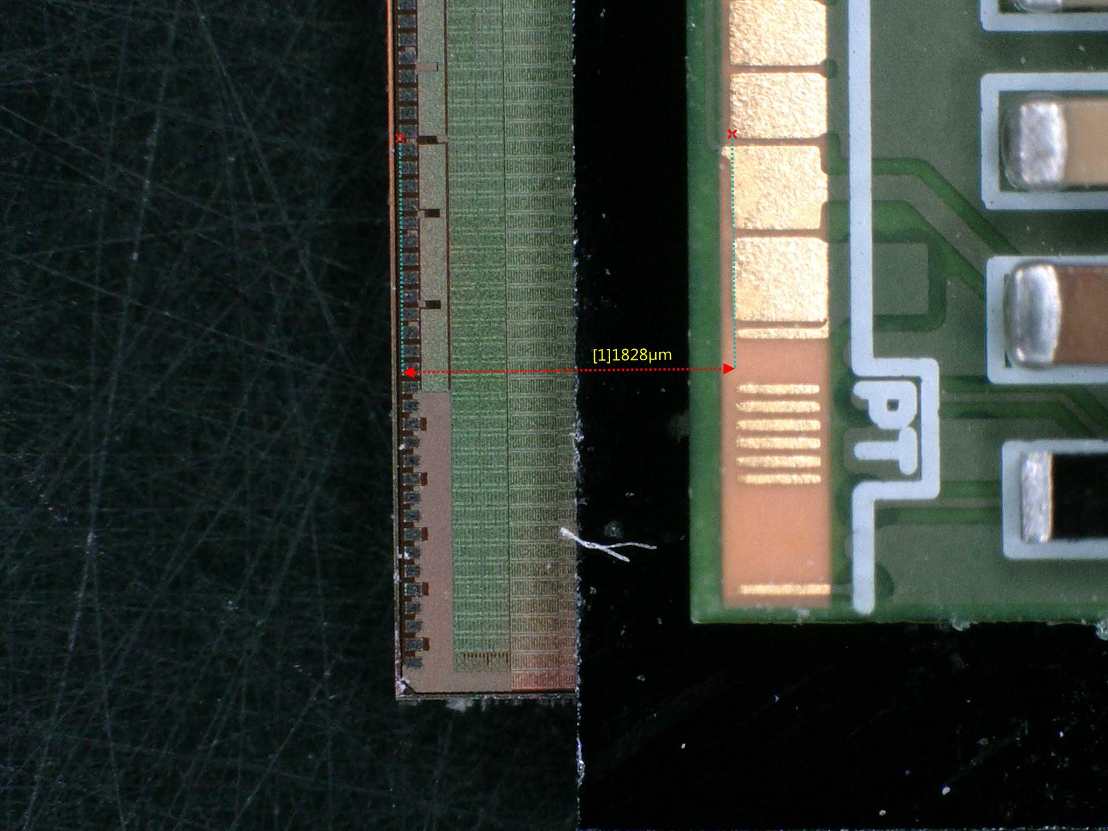
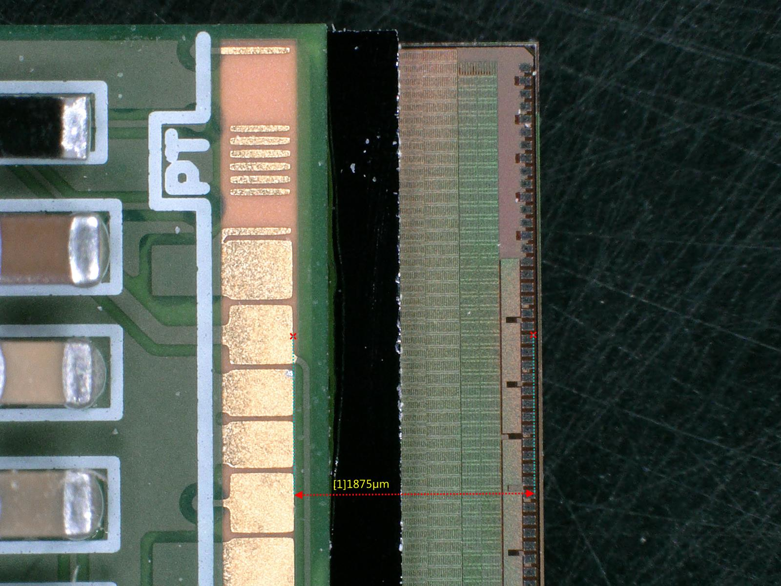
Measured the alignment of the two assembled module (one module was assembled during my last visit) using the microscope. The discrepancies in the distance between HDI wire-bond pads and ROC wire-bond pads are around 200 microns. If we take the length of the module to be 4cm, this is less than half a degree of tilt.
Worked on presentation reporting these activities for the tracker week. |
|
|

|
|

|
|