 Thu Oct 31 16:48:51 2019, Matej Roguljic, Module assembly, Phase 2 module gluing - preliminary observations Thu Oct 31 16:48:51 2019, Matej Roguljic, Module assembly, Phase 2 module gluing - preliminary observations
|
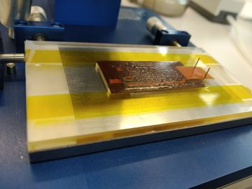
1 hour after applying glue to the HDI and gluing it to the sensor + ROCs, we took a look to see if the glue distribution was good. Unfortunately, the very edges on the long side didn't get glue so they are "bending" away from the sensor. This is bad since the wire bond pads are on these edges and if they're not properly glued, wire bonding will not be possible.
This happened because the glue stamp is narrower than the glue and we used a pretty viscose glue (Araldite). To remedy this, either a wider glue stamp needs to be used or a more liquid glue.
The module was put back on the jig with a weight on top of it to let it cure. Perhaps it will still be properly glued after more time passes. |
 Wed Oct 30 16:45:03 2019, Matej Roguljic, General, FC7 nanoCrate assembly Wed Oct 30 16:45:03 2019, Matej Roguljic, General, FC7 nanoCrate assembly   
|
| An FC7 nanoCrate was assembled on 30.10.2019. It houses one Imperial College adapter card and one FC7 FPGA board. It will be used for p2 module readout. |
 Wed Oct 30 12:23:08 2019, Matej Roguljic, Module assembly, Phase 2 dummy module gluing 19x Wed Oct 30 12:23:08 2019, Matej Roguljic, Module assembly, Phase 2 dummy module gluing 19x
|
-Phase 2 dummy module consists of a phase2 HDI, piece of silicon cut to the sensor size and 4 phase2 ROCs. For our first dummy module, 2 ROCs labeled "Red" were used, 1 labeled "yellow" and 1 labeled "green". The one labeled "green" was put as ROC0 of the module. Procedure is the following:
1) Head which can hold 4 ROCs with vacuum was put on a lift jig
2) Silicon cutout was placed on a module holder chuck. The chuck was "modified" by putting some tape over the holes and to align the silicon with the help of the tape as well. Vacuum on the chuck is then turned on to fix the "sensor" in place
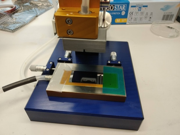
3) The chuck holder with sensor was placed on the base plate of the jig. Alignment with the head was made by lowering the head to the sensor and adjusting the micrometer screws. The numbers on the screws were noted after alignment: Top two = 4.80, Left = 3.65
4)Chuck holder with sensor was removed from the base plate and a ROC alignment plate, placed on top of a vacuum chuck, put in its place. ROC alignment plate was placed on top of a vacuum chuck because it is too thin and the head to hold the ROCs cannot reach it otherwise.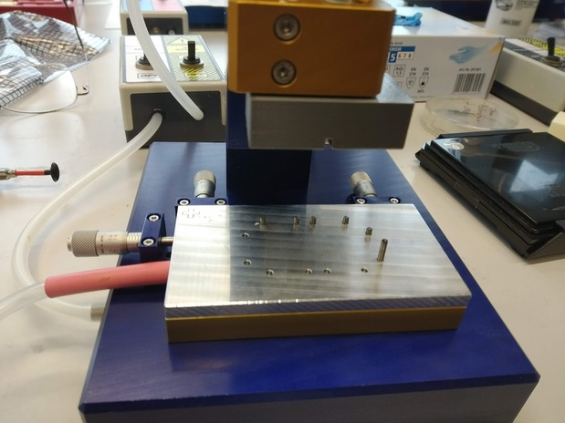
5) Adjustments with the micrometer screws were made so that the head just fits inside the "rectangle" made by the pins on the ROC alignment plate. The numbers on the screws were noted after alignment: Top two = 5.70, Left = 5.70 (they are the same by coincidence)
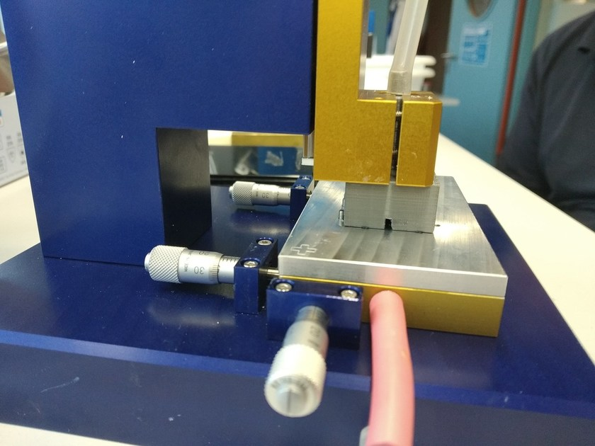
6) ROCs were placed on a ROC alignment plate. ROCs are placed face down, periphery to the outside. ROC0 (top right) was the "green" labeled" ROC.
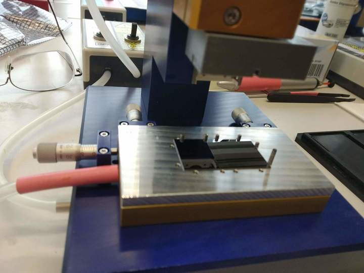
7) Head was lowered down to the ROCs, vacuum turned on and the ROCs were then lifted up.
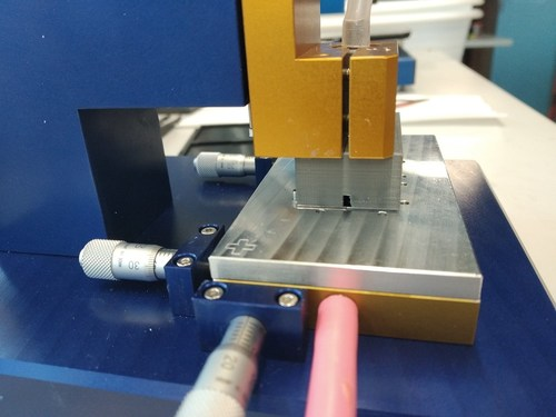
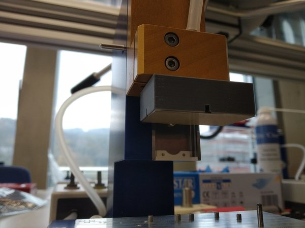
8) Micro-screws were set to values of sensor alignment (step 3) and the sensor placed on the jig base plate. Alignment was double-checked by lowering the ROCs to the sensor and inspecting the relative positions. Minor tweak was done at this stage, instead of using 4.8 on the top two screws, we used 4.7.
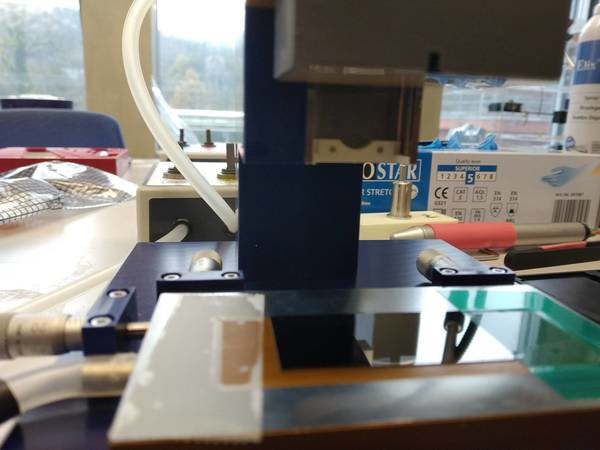
9) Araldite glue was mixed, spread in the glue bath and glue stamp was pressed into it.
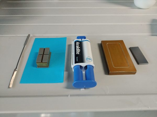
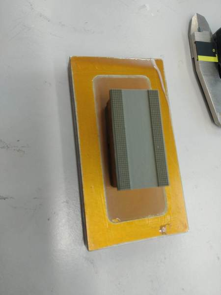
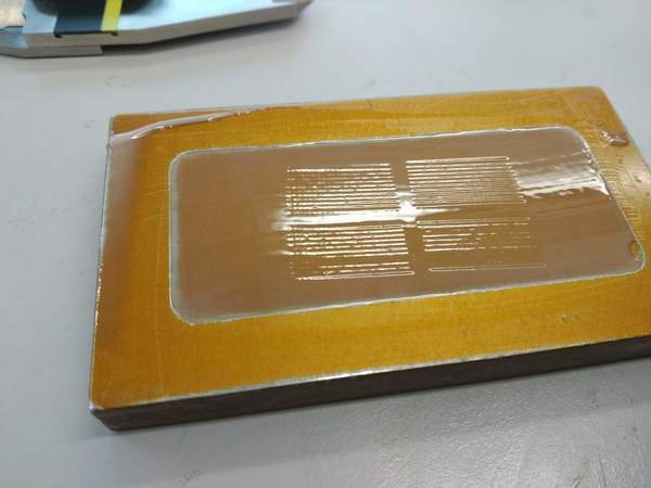
10) Glue stamp was manually pressed onto the sensor. This was the most tricky part of the procedure. Gluing stamp is just barely narrower than the sensor and it is quite difficult to center it properly. Furthermore, the chuck holding the sensor can easily move since the tension of the vacuum tube is exerting some force onto it. It is recommended to fix the sensor chuck on a heavier vacuum plate next time.
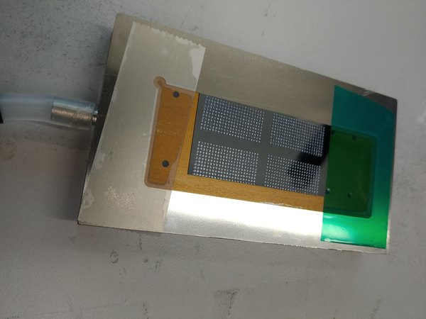
11) The sensor chuck was placed on the lift base plate, head holding the ROCs was lowered onto the sensor. Vacuum holding the ROCs was then turned off. A small weight was placed on top of the head to press it down.
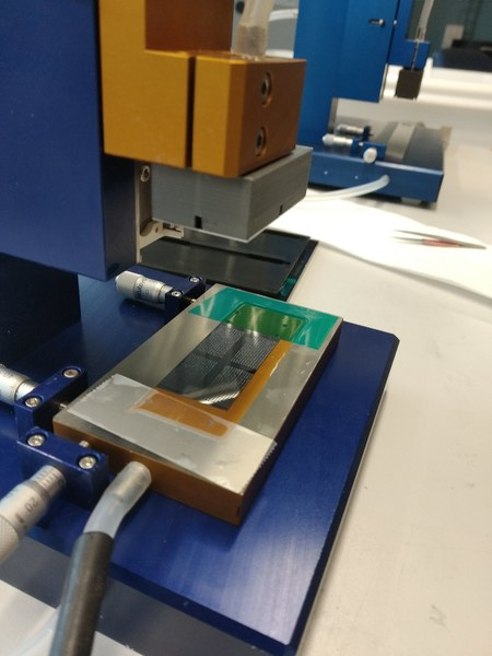
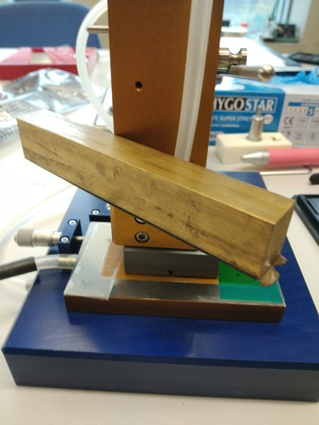
Glue was left to cure over the night. The next day HDI was glued to the sensor with the following procedure:
1) Sensor with ROCs was sucked to the head holding the ROCs, ROC side up ( HEAD-ROCs-Sensor).
2) HDI was placed on a chuck and the chuck was placed on the base plate of the lift holding the ROCs and sensor.
3) Micrometer screws were tuned so that the HDI is centered on the ROCs/sensor in the y direction and the cable-side edge of the HDI aligned to the edges of ROC 0 and ROC 3. (x actually didn't need alignment due to the dimensions of the ROC chuck and HDI chuck).
4) Glue stamp was fixed on a 3-d printed head, position of the stamp is quite important since the alignment pins of the HDI will prevent contact with the stamp if it's pressed in a wrong corner. The head along with the glue stamp was mounted on a second lift stage.
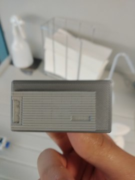
5) Chuck with HDI was placed on a base plate of the second jig and aligned using micrometer screws so that the gluing stamp hits the HDI well-centered. After alignment, it was removed to make space for the glue bath.
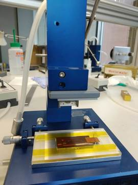
6) Araldite glue was applied to the glue bath, placed on the base plate of the second jig and the glue stamp was lowered to it to pick up the glue.
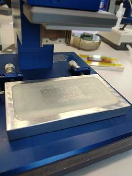
7) Glue bath was removed and HDI chuck put in its place. Glue stamp was lowered onto the HDI to apply the glue.
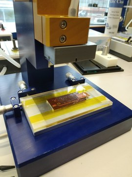
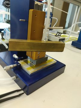
8) HDI chuck was then moved to the first jig after which the head, holding sensors and ROCs was lowered. Vacuum holding the ROCs was released. Small weight was placed on top of it to improve the contact.
 |
|