| ID |
Date |
Author |
Category |
Subject |
|
3
|
Tue Aug 6 16:01:17 2019 |
Matej Roguljic | Software | Wrong dac settings - elComandante | | If it seems that elComandante is taking wrong dac settings for tests like Reception test or full qualification, one should remember that it does NOT read values from module specific folders like "M1523", but rather from tbm-specific folders like "tbm10d". The folders from which the dacs are taken are listed in "elComandante.config", the lines which look like "tbm10d:tbm10d". |
|
4
|
Tue Aug 6 16:06:45 2019 |
Matej Roguljic | Other | Vsh and ctrlreg for v4 chips | | The recommended default value for Vsh is 8, but the current version of pXar has it as 30. One should remember this when making new configuration folders from mkConfig. The recommended value of ctrlreg is 17. |
|
5
|
Wed Aug 7 11:49:07 2019 |
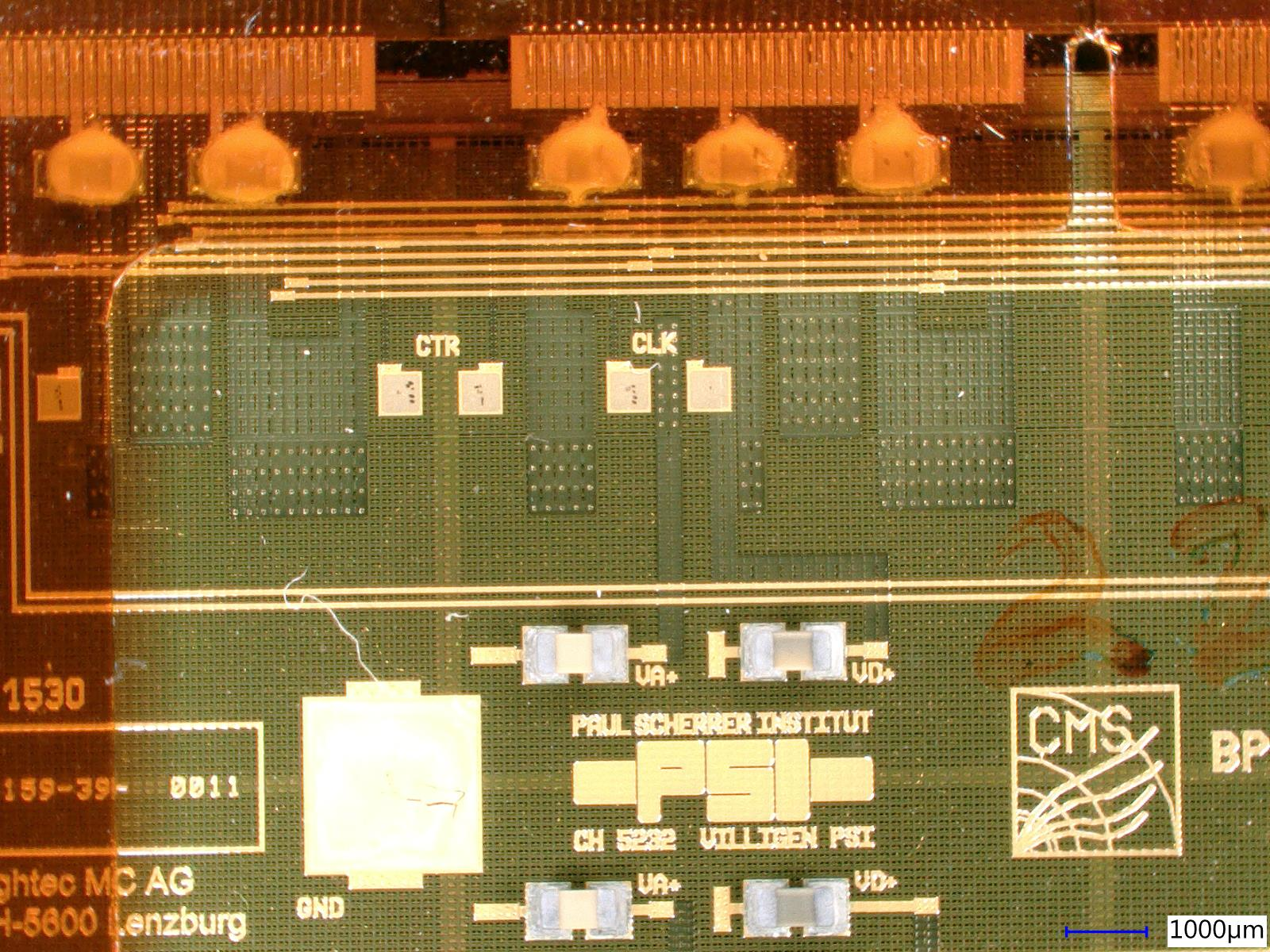
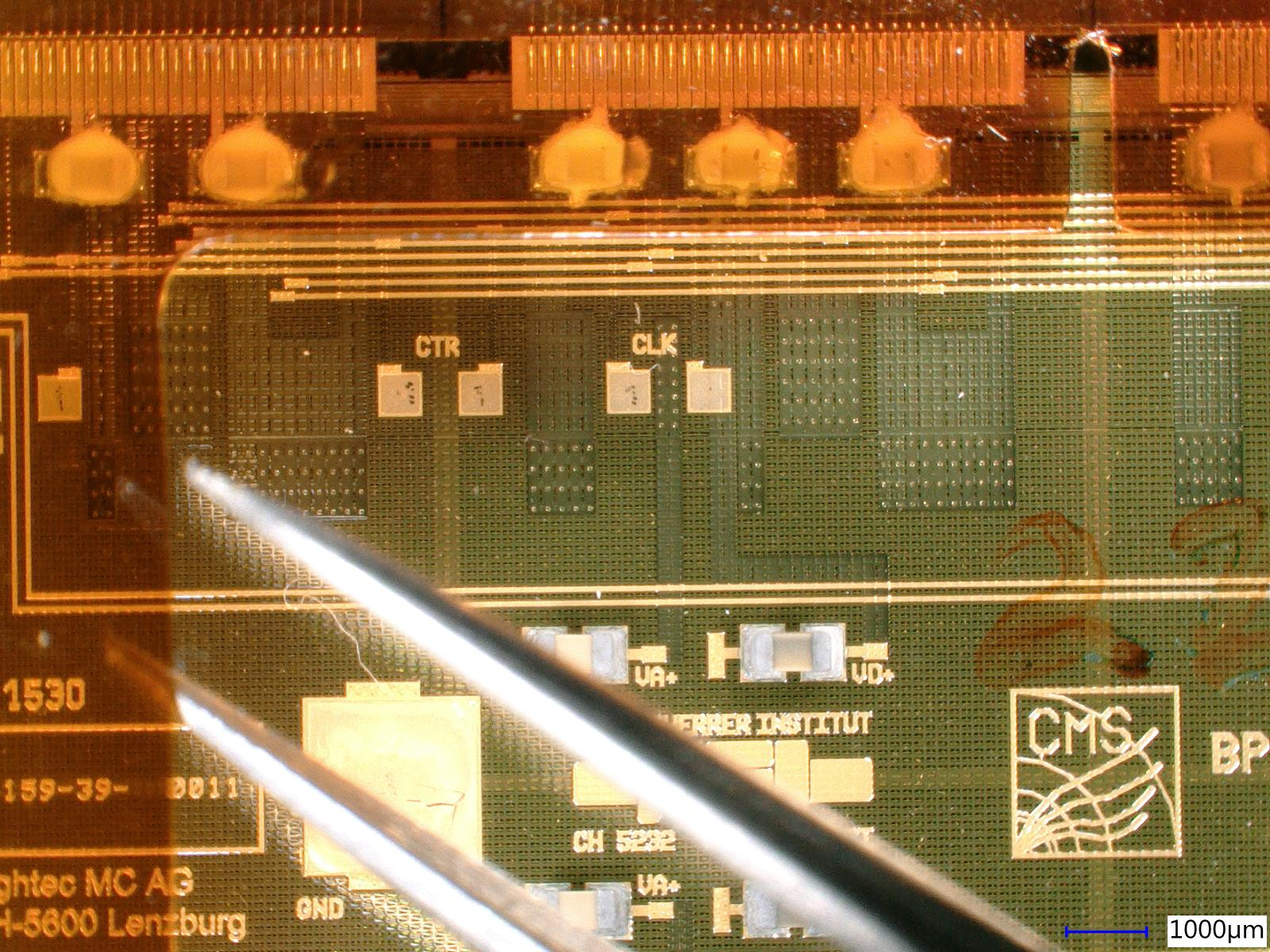
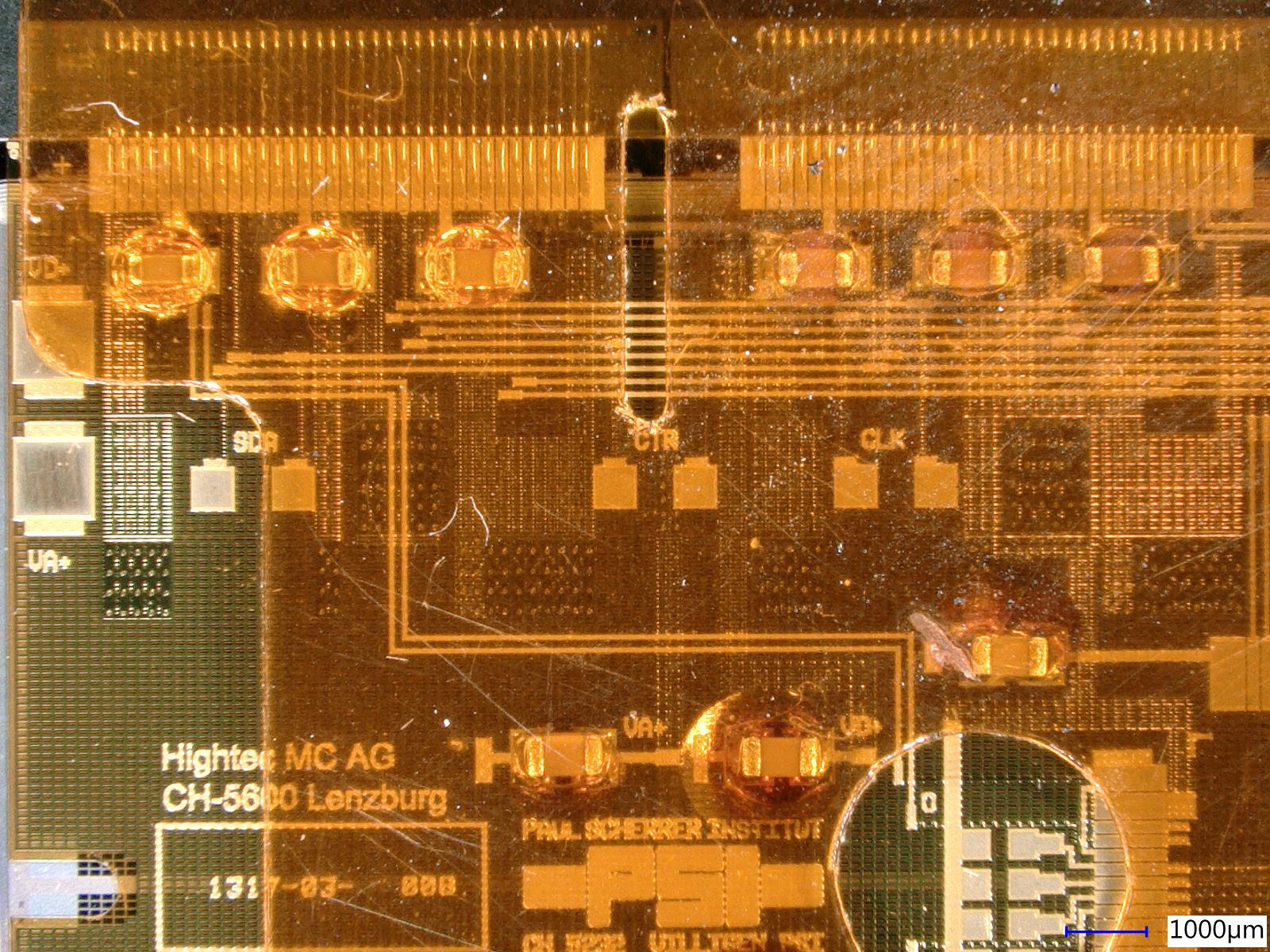
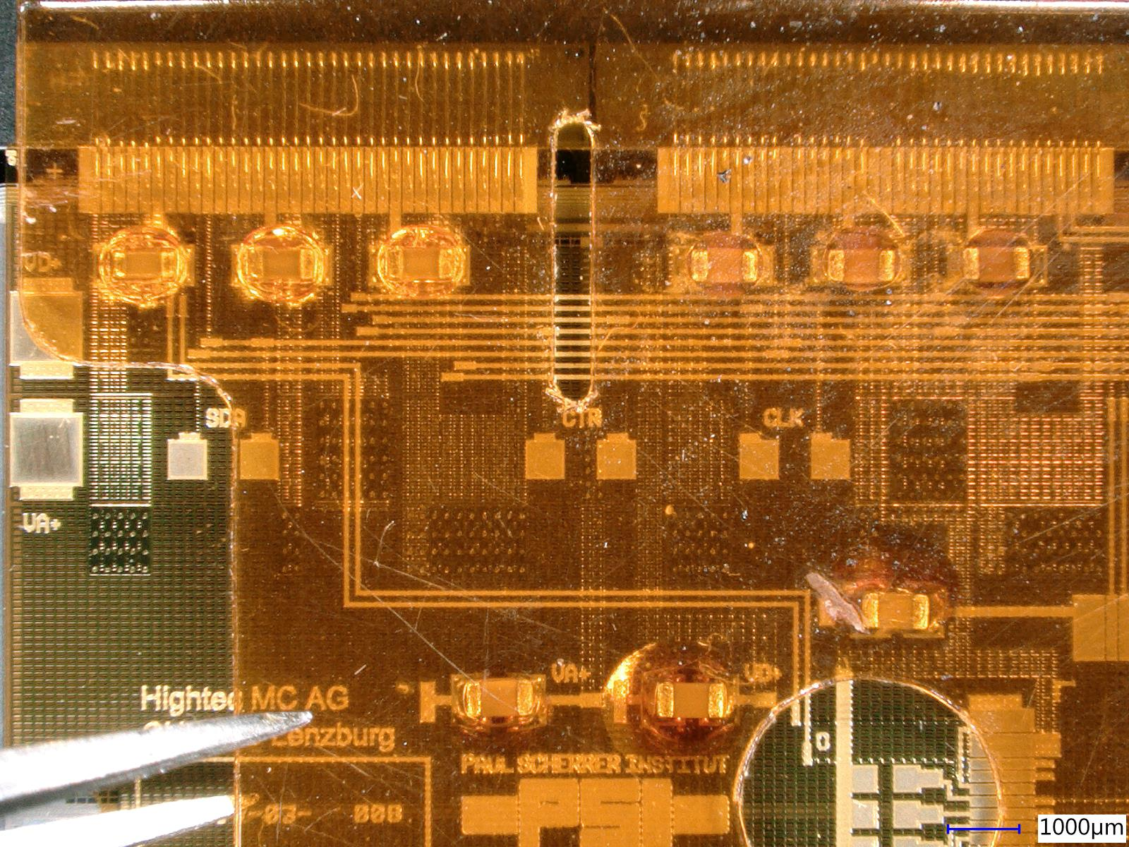
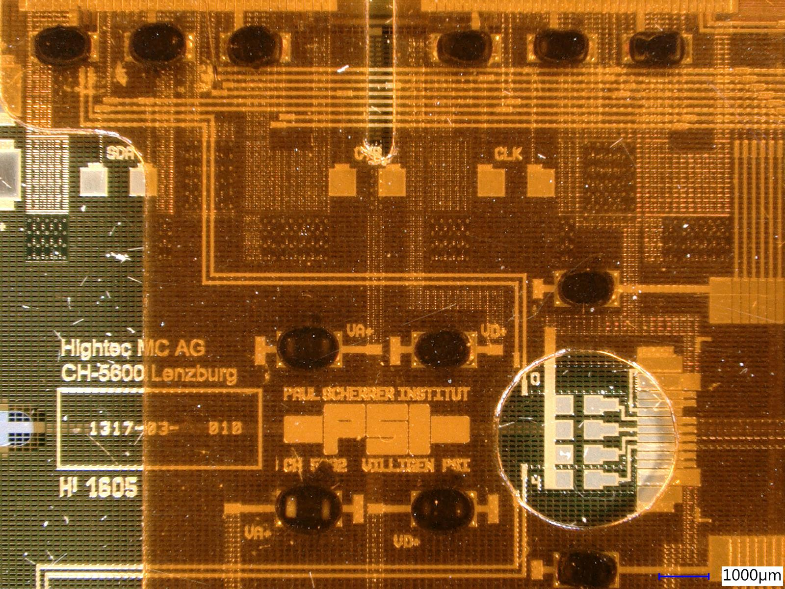
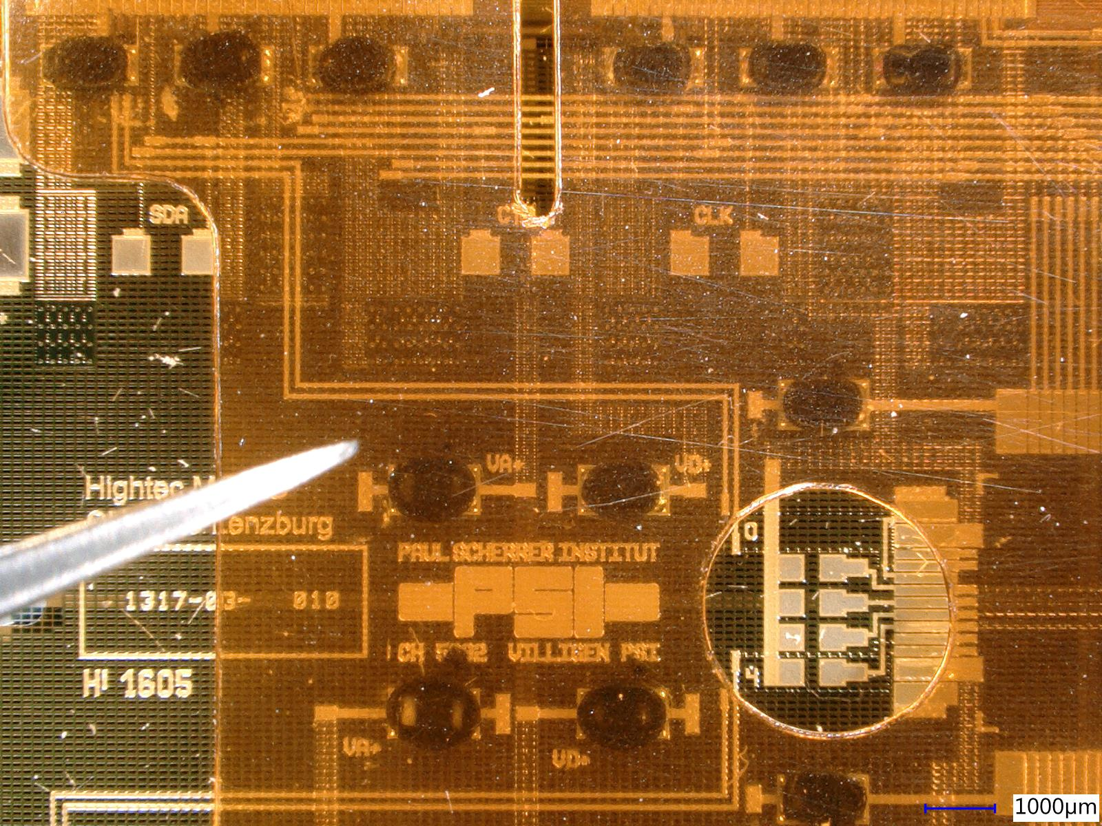
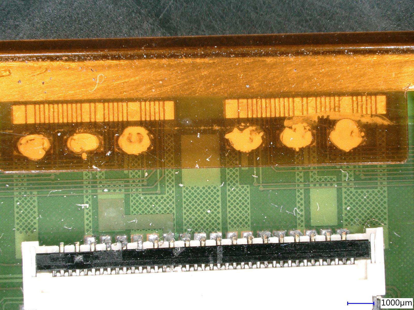
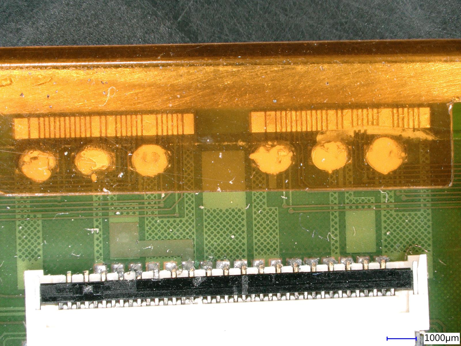
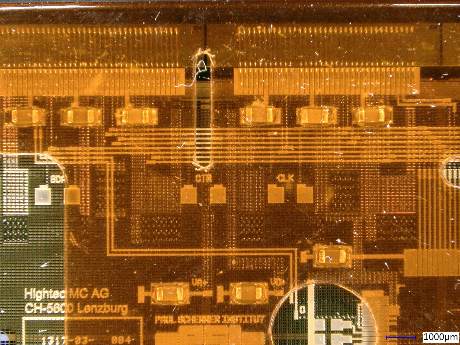
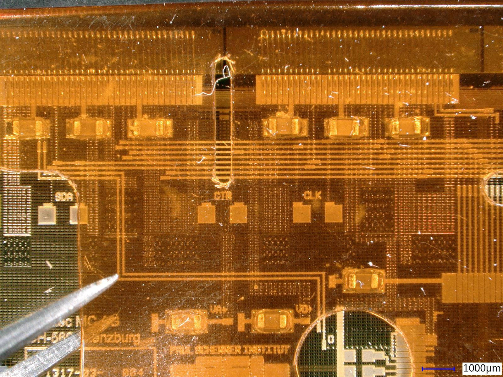
Matej Roguljic | Module assembly | HDI glue irradiation tests | Six different glues were used to glue the cap on six dummy modules. They were all irradiated to 120 MRad in Zagreb after which they were taken to PSI and tested with the tweezers under the microscope.
Standard glue (Dow-cornig), used in CMS - it became "two-component". Solid part on the capacitors and the liquid part on the cap. Surface tension was actually holding the cap quite strongly. Silvan deemed it the second best glue
Two component epoxy adhesive - the strongest glue out of all tested. The only drawback of it was that during the application of the glue to the capacitors, it left puddles around some of them since it is quite liquid before curing. This might have been prevented if we had a proper glue stamp. The glue stamp used at the time contained too much excess glue, and if another one was printed, with small grooves where the capacitors are, the amount of glue transferred should be lower and no puddles should appear. This glue was graded the best of all the tested glues. EDIT: the glue stamp with smaller grooves was printed and now there are no puddles anymore.
SG-20 (black) - sticks, but not really well. It was also quite soft and malleable. Because it doesn't stick very well, it is not recommended for gluing the cap.
WS-200 - almost identical to the SG-20, just a different color.
Terosan MS939 - doesn't stick, not recommended.
Ergo 6521 - doesn't stick, not recommended.
Took photos of them under the microscope. There are two photos for each glue. First one is while the cap is at rest, while on the second there is an upwards force applied with the tweezers. All of them except the two component epoxy adhesive detached when force was applied. With the epoxy adehsive, the module started lifting, but the glue held. |
| Attachment 1: dowCornig_con.jpg
|
|
| Attachment 2: dowCornig_split.jpg
|
|
| Attachment 3: epoxy_2component_con.jpg
|
|
| Attachment 4: epoxy_2component_split.jpg
|
|
| Attachment 5: sg20_con.jpg
|
|
| Attachment 6: sg20_split.jpg
|
|
| Attachment 7: terosan_ms939_con.jpg
|
|
| Attachment 8: terosan_ms939_split.jpg
|
|
| Attachment 9: ws200_con.jpg
|
|
| Attachment 10: ws200_split.jpg
|
|
|
6
|
Wed Aug 7 12:24:14 2019 |
Matej Roguljic | Documentation | Activities 31.7.-9.8.2019. | 31.7.
Matej tested 4 HDIs (8030-8033 and 8010). 8010 had a faulty TBM which was replaced, however, during subsequent tests, other TBM (the one which was working fine!) started sparking during HV test. Burn marks visible under the microscope in the top-right corner of the right TBM, between wire-bond pads. Other HDIs were fine and were glued to 2 v4 modules (1523 and 1529) and 1 v3 module (1526).
1.8.
Prepared the software and hardware for the full-qualification of multiple modules in parallel. Ran reception test on M1520 and M1522.
2.8.
Ran full qualification on M1520 and M1522. It consisted of qualification at -20, IV@-20, 5 cycles between -20 and +10, qualification at -20, IV@-20, qualification at +10 and IV@+10. This set of tests will from now on simply be called "full qualification". For some reason, second qualification at -20 failed. M1522 shows significantly high leakage current compared to previous tests
5.8.
Boxes 2 and 9 have been filled with L1 module trays. Each tray can hold 4 modules and each box contains 13 trays. Box 9 filled with humidity collecting balls. M1520 and M1522 placed in the box 9 which is the box that should be filled first. Reception test was run on M1523 and M1526. There were a lot of issues with M1523 in the address decoding test affecting other tests as well. What was found out is that the third dac, Vsh, was set to the wrong value by default if one was making module configuration folder using mkConfig script. It was 30 and should be 8. This should be propagated in pXar later on.
6.8.
Started running reception tests with 3 modules (1523,1526,1529) in parallel, but with the corrected value of Vsh (8). Several issues were observed.
First, one of the DTBs had a connection timeout which appeared every time we tried the reception test. Changing the DTB didn't work. This was solved by plugging the USB cable on the PC side to a different USB slot
Second, pretest in the reception test did timing test which we deemed unnecessary so it was removed.
Third, results for 1523 and 1529 didn't look correct. It was as if there was a problem with either timing or dac values. Comparing the logfiles of the test and the pxar files, it was found out that the timing settings were correct. The issue was in the dac settings taken by elComandante. What we forgot was that elComandante does NOT take dac settings frmo the module folder, but rather from generic tbm folders like tbm10d. This is set in the elComandante.config. The issue was that tbm10d folder had wrong values for Vsh (30, instead of 8) and ctrlreg (0 instead of 17). After this correction reception tests ran fine.
PixPhOptimization.cc was edited to correct the starting values of the parameters for the PhOptimization test. The old values were sometimes causing the tests to algorithm to fail even though the chip was fine.
Started full qualifications of all 3 modules, but there were some issues with the coldbox. It was noticed when it was not cooling at the start of full characterization. The warning on the coldbox interface read "Geber-stillstand". Danek managed to make it go away by stopping the program, even though no program was being run.
Finally, full qualification started around 15:00, finished at 22:40.
M1523 failed first qualification at -20, but finished other two qualifications. IV curves for that module were taken while M1529 was stuck and connected to HV as well meaning that the readings are actually sum of IVs from these two modules.
M1529 failed first qualification at -20, few seconds apart from M1523 failure. One of them failed during the Gain Pedestal, other one on PhOptimization. It also failed other two qualifications (PhOptimization and GainPedestal)
M1526 had no issues in qualification, however, it was graded C. One chip was problematic in most of the tests, while 4 others had issues with TrimBits. This is a bit suspicious so we'll investigate it further.
7.8.
Investigating problems with qualifications on testboards 0 and 1. We noticed that it happens during PhOptimization or GainPedestal. Also investigating why M1526 failed trimbits test on several ROCs. The cause was identified as a memory leak (several Gbs!) during a PhOptimization scan. Separate log made for this.
8.8.
Started full qualification WITHOUT PhOptimization at 9:15 on modules 1523, 1526, 1529. Finished after 8 hours. 1529 had a reception test error during fulltest@+10, other tests ran fine. Glued protection caps on 4 modules - 1504,1505,1509,1520 using 2 component epoxy adhesive.
9.8.
Running fulltest@-20 and +10 for modules 1504, 1505, 1520. The plan is to irradiate them in Zagreb and evaluate the changes induced by radiation. |
|
7
|
Wed Aug 7 18:01:06 2019 |
Matej Roguljic | Cold box tests | PhOptimization problem | | August 7 - we found out that PhOptimization algorithm starts leaking memory if it fails to find proper values. If running one setup, the test might go through. However, if multiple modules are tested in parallel and they all start leaking memory at the same time, the system will kill one testboard process (or two if necessary), causing the unlucky testboard(s) to get stuck (powered on, HV on, but no tests running) until they are reset. Current solution to this problem is to simply omit the PhOptimization if the fulltest procedure. We left gainPedestal, since it will use default Ph dac values. |
|
8
|
Tue Sep 10 15:18:20 2019 |
Matej Roguljic | Other | Modules 1504, 1505, 1520 irradiation report | | Modules 1504, 1505 and 1520 were taken to Zagreb for irradiation on 13.08.19. The goal was to check the v4 behavior after irradiation. They were irradiated to 1.2 MGy and returned to PSI on 9th of September. Upon testing them at PSI, they all had issues. ROCs on M1504 and M1520 were not programmable at all, changing Vana had no effect. Vana could be set on M1505 while targeting Iana = 28 mA/ROC, however, no timing could be found for it and no working pixel could be found. Andrey and Matej took the modules under the microscope and saw a "greenish" deposits on HDI metal pads of unknown origin. There was also a bit of liquid near the HDI ID on M1520, but not on others. The residue could be shorting some pads causing issues on the module. It is still unclear whether the residue comes from the HDI, cap or is it introduced during irradiation by something in Zagreb. |
|
9
|
Thu Sep 12 10:32:27 2019 |
Matej Roguljic | General | Activities 10.9.-19.9.2019. | 10.9.
Modules 1504,1505,1520 brought to PSI after irradiation to 1.2 MGy in Zagreb. All 3 were not working when put under test with pXar. 1504 and 1520 couldn't set Vana at all. 1505 could set Vana, but timing couldn't be found and pixels weren't responding. Inspection under the microscope showed some "white-greenish" deposits on the metal pads on the HDIs which are most likely shorting the ROC pads causing the module to be non-responsive
11.9.
Removed cap from 1504 to take a better look under the microscope and some photos. The good news is that the glue holds really well. The deposition looks like a crystal growth. It reminded Danek of the humidity issues they had at CERN in 2014. Touching it with a needle showed that it is not completely solid, like "wet-snow", however, on some pads, the deposition was more solid. There was also small transparent liquid deposits observed. Prepared 3 modules for cap gluing training; 1047, 10X1, 10X2. Only 1047 works (partially) and Reception test was performed on it. Two gluing jigs prepared in the assembly lab.
12.9.
Ran reception on 1509, it will go to ETH for irradiation (not really sure if it's ETH). Further tested modules 10X1 and 10X2. X2 should have hubID set to 17,25 after which the ROCs are programmable, however, there is no readout. X1 should have hudID 31,30; but only TBM with hubID 30 works, ROCs are programmable, but no readout as well. Glued protection cap to a module 10X1. Roughly 4 minutes after the start of mixing, the glue starts to become fairly solid which gives us a constraint on the time it takes us to apply it to a module.
13.9.
Glued caps on 1508 and 1047 using the jig further from the entrance door of the assembly lab. 1508 was glued first and had an asymmetrically placed cap (one side of the cap quite close to the wirebonds). The stage was adjusted so the cap glued to 1047 was properly placed. An unused HDI was found 8-011, it was tested and found to be working until the HV test where it started sparking at -1000V, similar to 8-010. There are burn marks visible under the microscope on the same position as the ones on 8-010.
16.9.
Investigated further the sparking issue with the HDIs. Ed Bartz took a look at the photos and identified that the damaged part of the TBM is the protection diode of pin 46.
17.9.
Equipped the coldbox with 4 DTBs which makes it possible to do qualification on 4 modules at the same time. Investigated phase2 ROC-HDI gluing jig. |
|
11
|
Wed Sep 18 15:45:45 2019 |
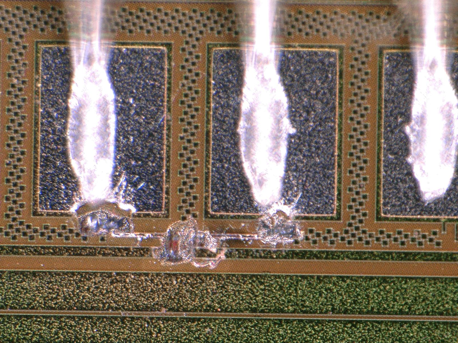
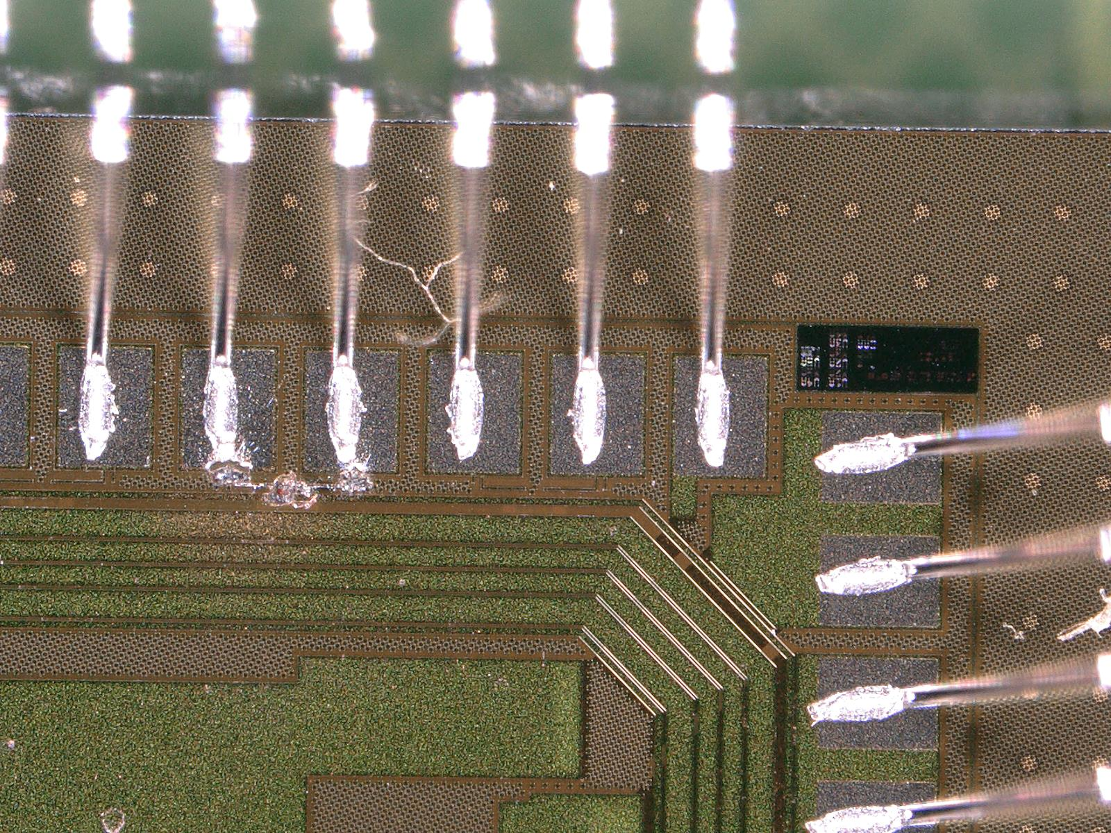
Matej Roguljic | Module assembly | HDI sparking under HV test | HDI 8010 passed all test except the HV. Under the HV test, some sparks could be heard and even seen by eye on the right TBM (closer to the HV pad!). Testing it again, showed that it was indeed damaged by the spark. Sparking craters could be seen with the microscope between pads 4 and 5 of the TBM.
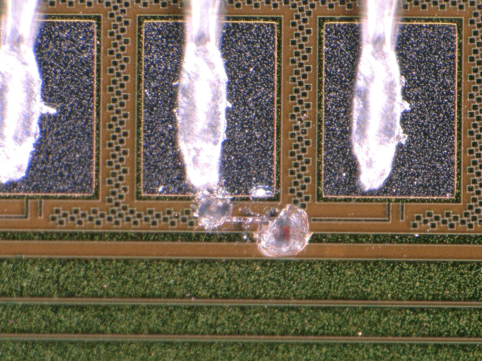
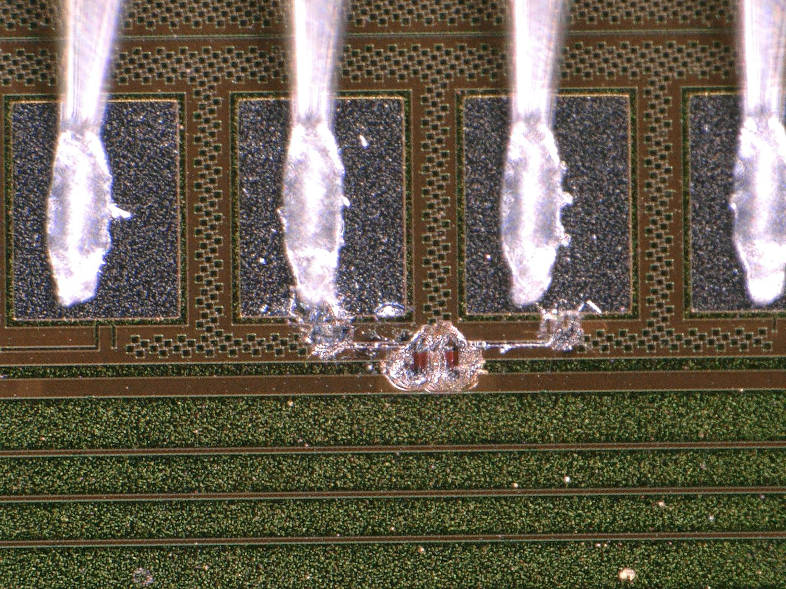
The same thing happened a month later, on HDI 8012. Again, it passed all the test until HV when sparks appeared and damaged the TBM, and, curiously enough, the damage was on the same position on the TBM as with 8010.
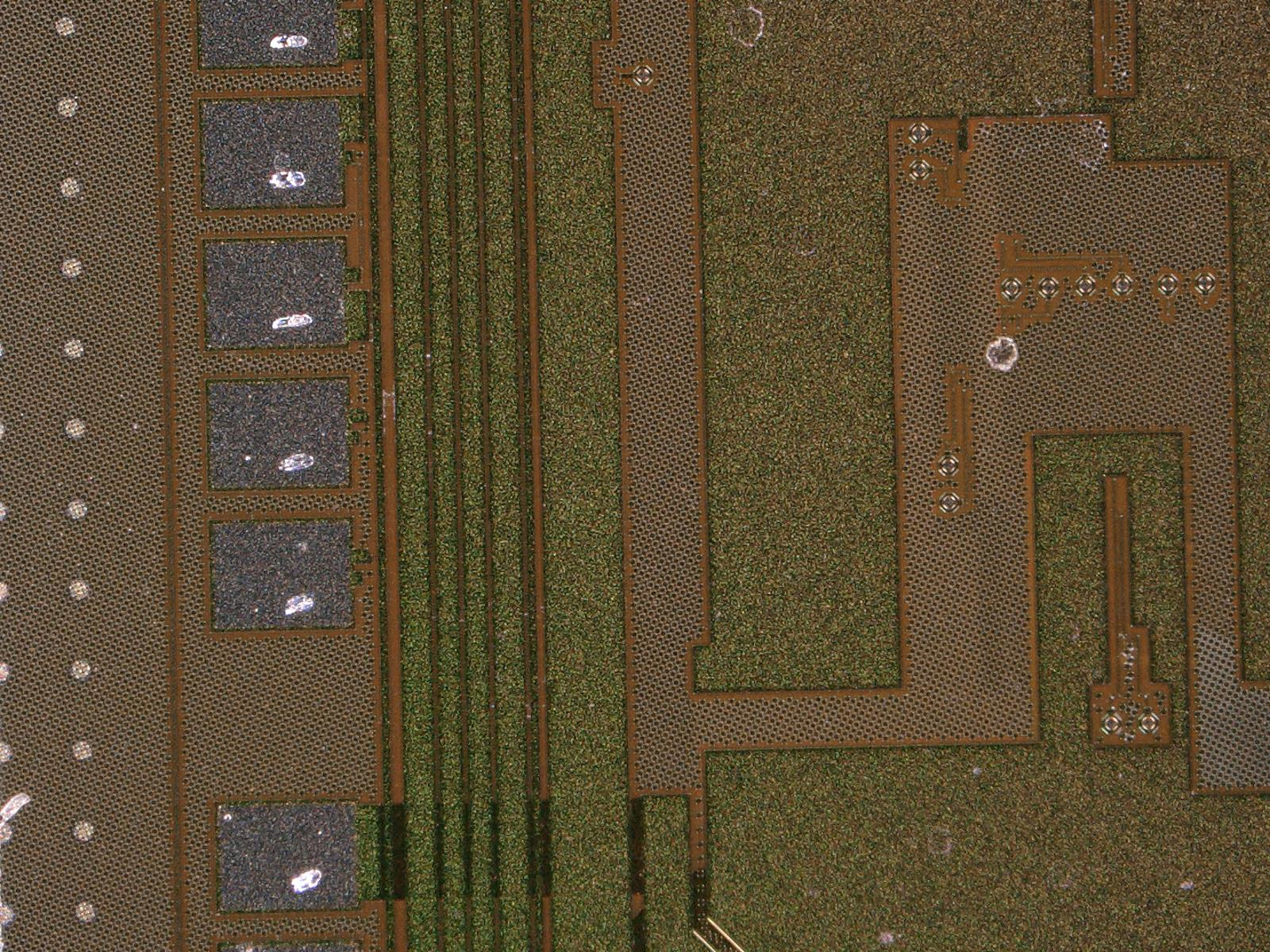
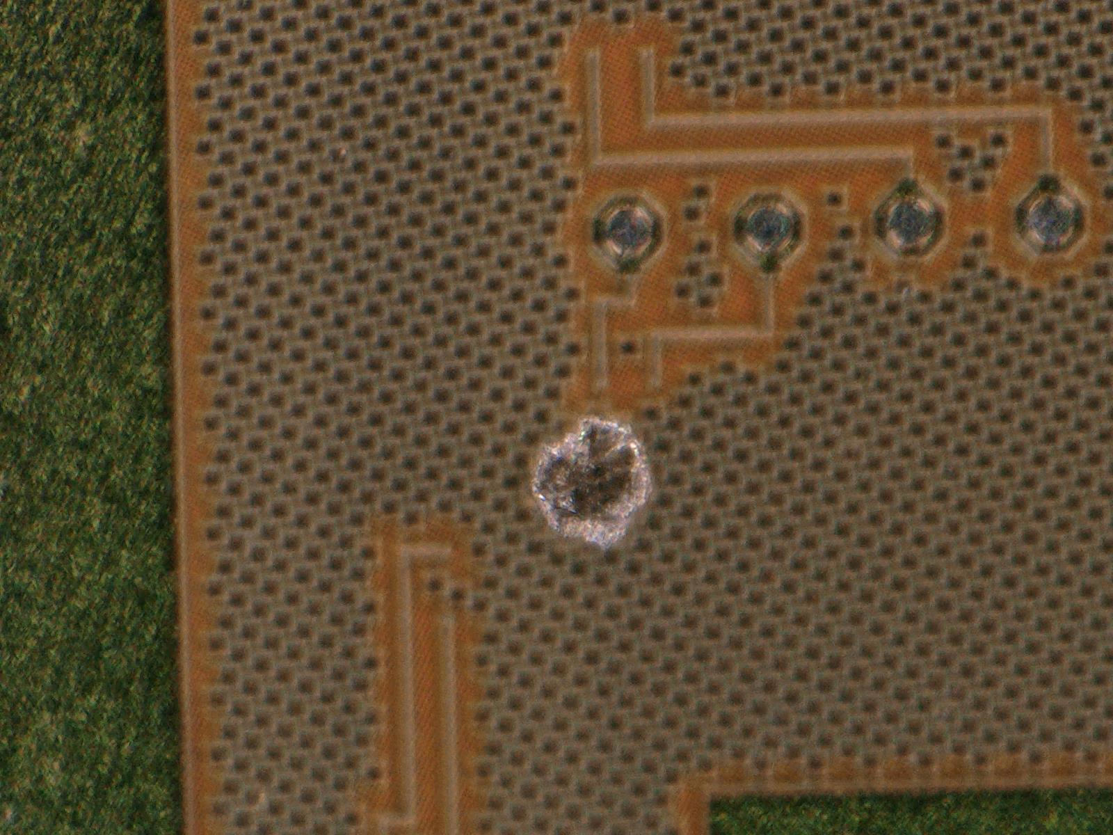
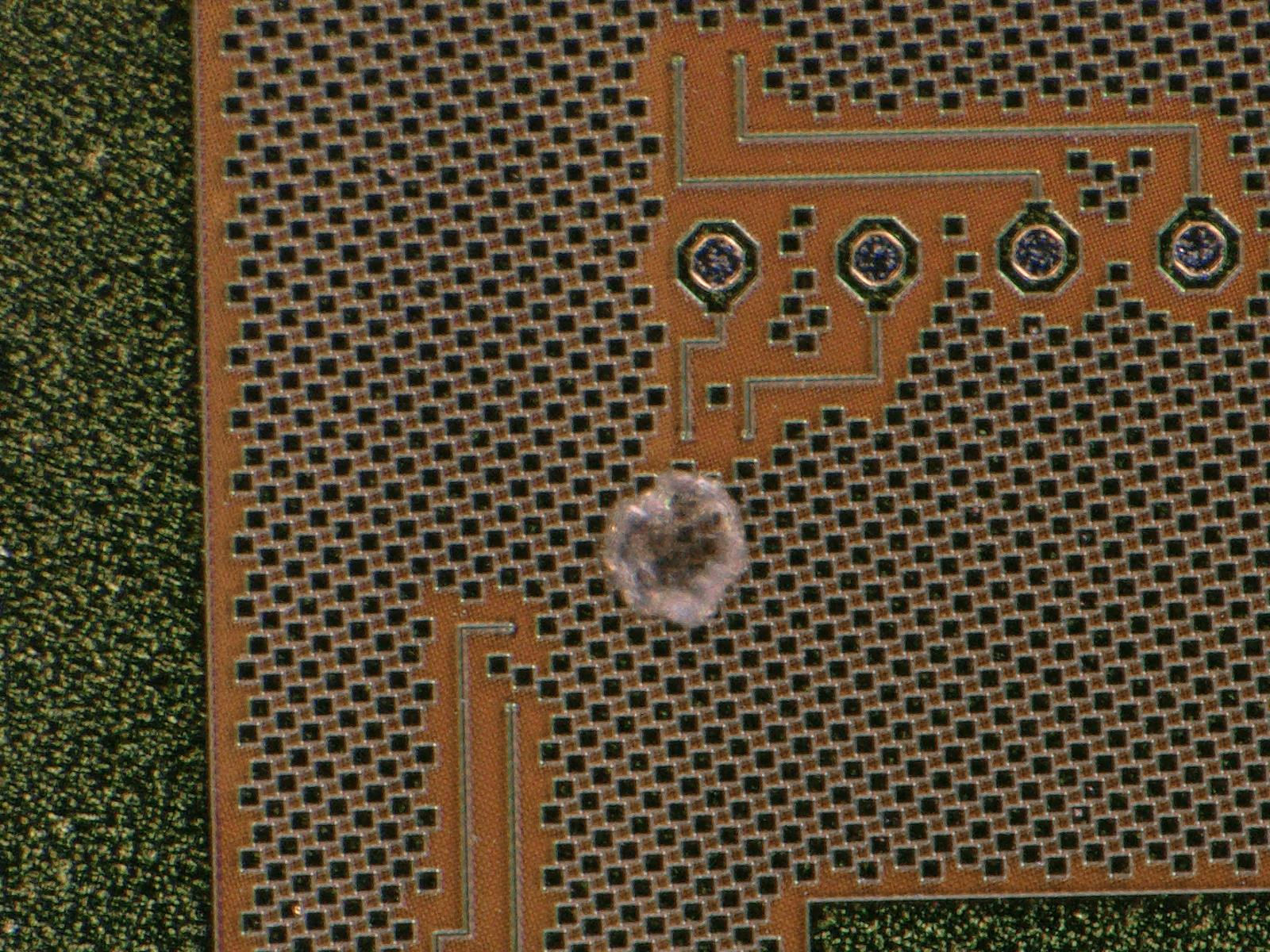
HDI 8011 was put under the HV test as well, however, this one didn't have any wires bonded to the TBMs because gold plating was missing on several of the wire bonds. Sparking could be heard, but we couldn't located where the damage happened. There is one potential candidate, shown on the photo attached to this log entry.
On 18.09. a possible explanation for the sparking was thought of. Wolfram and Matej put one of the "faulty" HDIs under HV test and noticed that sometimes a spark could be seen between the HDI handle and the aluminum base plate! It looks like the HV pin rests near the border of the HV pad and the ending of the HDI. Because of that, there is a discharge from the HV pin to the HDI handle. The discharge connects to the ROC wire bond pads closest to the HV pad providing a way to affect the TBM! This is further strengthened by the fact that the damaged TBM pad is connected to the first four ROCs closest to the HV pad. To test this, we put kapton tape on the HDI handle, near the HV pad and tested the HDI again and there were no sparks.
The HDIs to be used for L1 replacement are slightly longer to prevent HV jumping to the sensor. Incidentally, this might also solve the sparking issue. If the issue is not solved on the longer HDIs, HDI holders will have to be further isolated in the region close to the HV pad. |
| Attachment 1: HDI_8010.jpg
|
|
| Attachment 2: HDI_8010_unzoom.jpg
|
|
| Attachment 3: HDI_8012.jpg
|
|
| Attachment 4: HDI_8012_2.jpg
|
|
| Attachment 5: HDI_8011_1.jpg
|
|
| Attachment 6: HDI_8011_2.jpg
|
|
| Attachment 7: HDI_8011_3.jpg
|
|
|
13
|
Thu Sep 19 14:20:07 2019 |
Matej Roguljic | General | Activities 10.9.-19.9.2019. |
| Matej Roguljic wrote: | 10.9.
Modules 1504,1505,1520 brought to PSI after irradiation to 1.2 MGy in Zagreb. All 3 were not working when put under test with pXar. 1504 and 1520 couldn't set Vana at all. 1505 could set Vana, but timing couldn't be found and pixels weren't responding. Inspection under the microscope showed some "white-greenish" deposits on the metal pads on the HDIs which are most likely shorting the ROC pads causing the module to be non-responsive
11.9.
Removed cap from 1504 to take a better look under the microscope and some photos. The good news is that the glue holds really well. The deposition looks like a crystal growth. It reminded Danek of the humidity issues they had at CERN in 2014. Touching it with a needle showed that it is not completely solid, like "wet-snow", however, on some pads, the deposition was more solid. There was also small transparent liquid deposits observed. Prepared 3 modules for cap gluing training; 1047, 10X1, 10X2. Only 1047 works (partially) and Reception test was performed on it. Two gluing jigs prepared in the assembly lab.
12.9.
Ran reception on 1509, it will go to ETH for irradiation (not really sure if it's ETH). Further tested modules 10X1 and 10X2. X2 should have hubID set to 17,25 after which the ROCs are programmable, however, there is no readout. X1 should have hudID 31,30; but only TBM with hubID 30 works, ROCs are programmable, but no readout as well. Glued protection cap to a module 10X1. Roughly 4 minutes after the start of mixing, the glue starts to become fairly solid which gives us a constraint on the time it takes us to apply it to a module.
13.9.
Glued caps on 1508 and 1047 using the jig further from the entrance door of the assembly lab. 1508 was glued first and had an asymmetrically placed cap (one side of the cap quite close to the wirebonds). The stage was adjusted so the cap glued to 1047 was properly placed. An unused HDI was found 8-011, it was tested and found to be working until the HV test where it started sparking at -1000V, similar to 8-010. There are burn marks visible under the microscope on the same position as the ones on 8-010.
16.9.
Investigated further the sparking issue with the HDIs. Ed Bartz took a look at the photos and identified that the damaged part of the TBM is the protection diode of pin 46.
17.9.
Equipped the coldbox with 4 DTBs which makes it possible to do qualification on 4 modules at the same time. Investigated phase2 ROC-HDI gluing jig. |
18.9.
Decided on a final HDI irradiation test. We will have an HDI without components in a bag filled with nitrogen (N2 bag), HDI with components in N2 bag, Dummy module (HDI with cap glued on it) in N2 bag, Dummy module not in an N2 bag and and an HDI with components cleaned by Silvan not in an N2 bag. The idea is to expose them to irradiation in a dry environment to check if there will be weird deposits on the metallic pads of the HDI. With the 2 samples not in an N2 bag we will see if there are some deposits again. To do so, before irradiation we will inspect them under a microscope and take photos and inspect them immediately after irradiation.
Furthermore, a possible explanation for the HDI sparking problem was devised and solutions, if necessary. It is described in more details in a separate log entry. |
|
15
|
Thu Sep 26 17:38:07 2019 |
Matej Roguljic | General | Activities 25.-26.9. | | It was planned to test a batch of HDIs these 2 days but the shipment was late. Dinko and Andrei were shown the HDI testing procedure. Matej further worked on the script used to test the HDIs. Dinko glued caps on 2 dummy modules and on M1522. New HDIs arrived on 26th and it looks like the kapton will have to be put underneath them during the testing to prevent sparking. |
|
23
|
Mon Oct 28 17:01:05 2019 |
Matej Roguljic | Software | Investigating the bug with the Keithley client | We took module 1529 and tried recreating the issue observed in the beginning of October. To do this in a reasonable amount of time, a "shorttest" procedure was defined which consists only of pretest and pixelalive. Three runs were taken
Run number 1: Shorttest@10,IV@10
Run number 2: Shorttest@10, IV@10,Cycle(n=1, between 10 and -10), Shorttest@10, IV@10
Run number 3: Shorttest@10, IV@10, Cycle(n=5, between 10 and -10), Shorttest@10, IV@10
In runs 1 and 2, IV was done from -5 to -155 in steps of 10
In run 3, IV was done from -5 to -405 in steps of 10
No issues were observed during the tests themselves.
Running MoReWeb shows the Temperature, Humidity and Sum of Currents plots while individual tests show only Pixel Alive map. IV plot is missing in the MoReWeb output, however, it is present in the ivCurve.log file. Tried investigating why IV is not shown, but couldn't get to the bottom of it.
Tomorrow we'll use M1529 and M1530 in a FullTest to check if the problem would appear. |
|
25
|
Tue Oct 29 16:36:23 2019 |
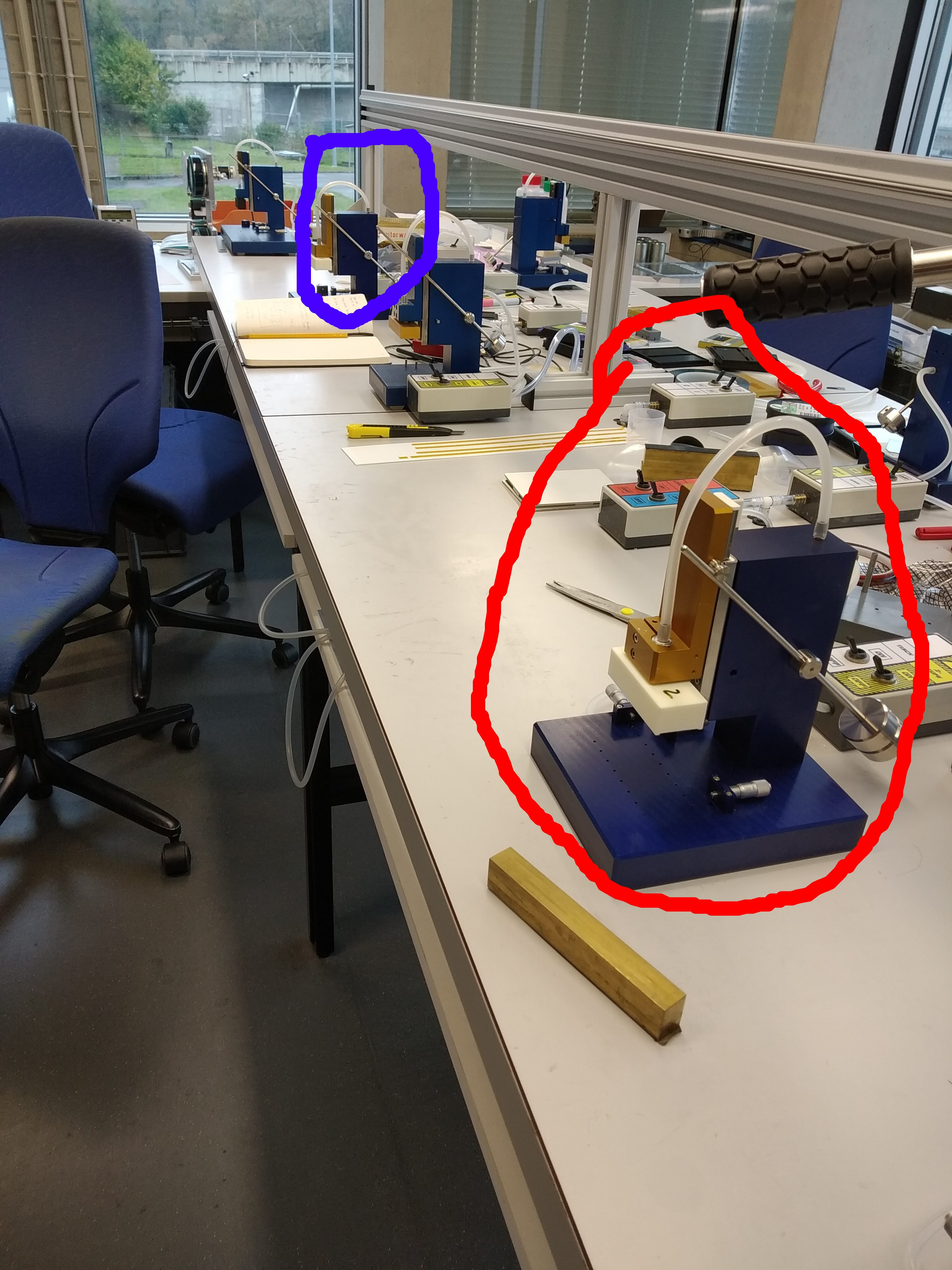
Matej Roguljic | Module assembly | Assembly lab cap gluing jigs | There are two jigs for cap gluing in the assembly lab, circled in red and blue on the photo in the attachment. The one closer to the door (red) we used to build glue Phase 2 HDI to a dummy sensor and four Phase2 ROCs. Before changing the head, the numbers of the alignment screws were noted.
The jig closer to the doors (red): Top two pins - 5.75; Left pin - 5.5
The jig further from the doors (blue): Top two pins - 5.71, Left pin - 3.25 |
| Attachment 1: IMG_20191029_150037.jpg
|
|
|
26
|
Tue Oct 29 16:38:32 2019 |
Matej Roguljic | Software | Investigating the bug with the Keithley client |
| Matej Roguljic wrote: | We took module 1529 and tried recreating the issue observed in the beginning of October. To do this in a reasonable amount of time, a "shorttest" procedure was defined which consists only of pretest and pixelalive. Three runs were taken
Run number 1: Shorttest@10,IV@10
Run number 2: Shorttest@10, IV@10,Cycle(n=1, between 10 and -10), Shorttest@10, IV@10
Run number 3: Shorttest@10, IV@10, Cycle(n=5, between 10 and -10), Shorttest@10, IV@10
In runs 1 and 2, IV was done from -5 to -155 in steps of 10
In run 3, IV was done from -5 to -405 in steps of 10
No issues were observed during the tests themselves.
Running MoReWeb shows the Temperature, Humidity and Sum of Currents plots while individual tests show only Pixel Alive map. IV plot is missing in the MoReWeb output, however, it is present in the ivCurve.log file. Tried investigating why IV is not shown, but couldn't get to the bottom of it.
Tomorrow we'll use M1529 and M1530 in a FullTest to check if the problem would appear. |
M1530 was put in the coldbox and qualification was started, but the pxar output was full of deserializer errors. The continuous stream of errors made the log file pretty large and slowed down the execution of the qualification so it was aborted. Later it was noticed that there are green depositions on the module like it was on the HDIs irradiated at 60Co facility in Zagreb which is probably why there were so many errors.
M1521 was used instead of M1530 along with M1529. Full qualification was launched around 11:00. |
|
27
|
Wed Oct 30 10:38:04 2019 |
Matej Roguljic | General | Activities 28.-31.10.2019. | 28.10. - Investigated a problem with the FullQualification setup, described more in this note
29.10. - Further investigated the aforementioned problem and worked on preparing the jigs for Phase2 dummy module building.
30.10. - Confirmed that the reported issue is not present at the moment on the qualification system. Glued dummy sensor to four phase2 ROCs. Built a FC7 nanoCrate. |
|
30
|
Wed Oct 30 16:54:58 2019 |
Matej Roguljic | Software | Investigating the bug with the Keithley client |
| Matej Roguljic wrote: |
| Matej Roguljic wrote: | We took module 1529 and tried recreating the issue observed in the beginning of October. To do this in a reasonable amount of time, a "shorttest" procedure was defined which consists only of pretest and pixelalive. Three runs were taken
Run number 1: Shorttest@10,IV@10
Run number 2: Shorttest@10, IV@10,Cycle(n=1, between 10 and -10), Shorttest@10, IV@10
Run number 3: Shorttest@10, IV@10, Cycle(n=5, between 10 and -10), Shorttest@10, IV@10
In runs 1 and 2, IV was done from -5 to -155 in steps of 10
In run 3, IV was done from -5 to -405 in steps of 10
No issues were observed during the tests themselves.
Running MoReWeb shows the Temperature, Humidity and Sum of Currents plots while individual tests show only Pixel Alive map. IV plot is missing in the MoReWeb output, however, it is present in the ivCurve.log file. Tried investigating why IV is not shown, but couldn't get to the bottom of it.
Tomorrow we'll use M1529 and M1530 in a FullTest to check if the problem would appear. |
M1530 was put in the coldbox and qualification was started, but the pxar output was full of deserializer errors. The continuous stream of errors made the log file pretty large and slowed down the execution of the qualification so it was aborted. Later it was noticed that there are green depositions on the module like it was on the HDIs irradiated at 60Co facility in Zagreb which is probably why there were so many errors.
M1521 was used instead of M1530 along with M1529. Full qualification was launched around 11:00. It ended around 6:30 without any issues. |
Running full qualification on 30.10. in the morning on modules 1510, 1529, 1521. Fourth module was not included since there was an issue with the 4th DTB which will be investigated late. Like the previous day, the qualification ended around 17:00 without issues. In conclusion, the issue is not present in the qualification setup at the moment. |
|
31
|
Thu Oct 31 10:41:12 2019 |
Matej Roguljic | Cold box tests | Issue with DTB_WWVASW | On 29th of October, an issue with DTB_WWVASW was noticed when trying to run FullQualification on 4 modules at the same time. On a tested, working module, setting Vana works but taking tornado plots (setvthrcomp) doesn't as well as other tests. Curiously enough, after switching the DTB with the one used for HDI testing (DTB_WRN13L) the problem was still there. This lead us to believe that the problem was with cables or ground. All cables and the adapter were tested and shown to be working fine. This is when we took a third DTB, put it in the same plae as previously WWVASW and WRN13L, connected all the cables and then the tests worked.
Conclusion of the tests is that DTB_WWVASW and DTB_WRN13L are suffering from the same failure mode. It was not noticed before on the WRN13L because it does not affect the HDI tests. This leaves us with 3 working DTBs for the FUllQualification tests. |
|
35
|
Wed Nov 27 08:39:24 2019 |
Matej Roguljic | Cold box tests | Bump bonding test investigation | | The BB test on M1534 shows a lot of dead bunmps on C10 and some on C1 and C0 as well. Putting a source on top of the module shows that the pixels for which the test showed dead bumps are still able to read hits from the source. Therefore, it looks like the bumps are working, but the test is reporting them as defective. It turns out that the bumps used by Helsinki are different than the bumps used at PSI so a different test needs to be used. After trying all 4 BB tets in pXar, it was concluded that BB2 is the appropriate test to use. |
|
38
|
Thu Nov 28 15:58:20 2019 |
Matej Roguljic | General | Activities 26.-29.11.2019. | 26.11.
Prepared the tools for RD53A digital module assembly in the assembly lab
Investigated if the latest pXar commit solved the issue with PhOptimization, now called Ph, and it runs successfully.
Investigated the bump bonding issue in which pXar reports bad bumps, but we suspected that was not the case. And indeed, putting a source on top of the chip reported to have bad bumps and taking data shows that there are no bad bumps as reported by pXar. Our conclusion was that the BB test developed by PSI is not applicable for bumps bonded by Helsinki. BB2 seems to be appropriate.
27.11.
Assembled a Phase 2 digital module using good ROCs - 1A48, 1A47, 1A43, 1A42; being ROC 0,1,2 and 3, respectively.
Used X-ray box to confirm our BB findings yesterday and the results agree that there are no defective bumps (as reported by pXar) on M1534.
28.11.
Took a look at the assembled module and it seems that one corner of the HDI was not properly glued. There are also solder marks on a couple of pads so we decided not to wire-bond it.
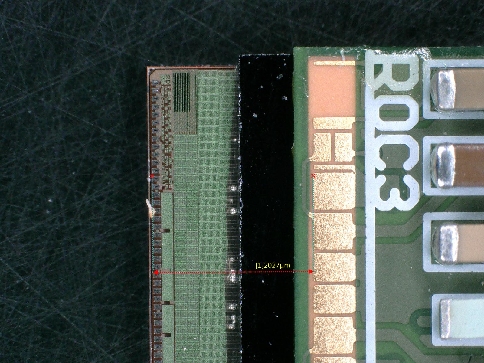
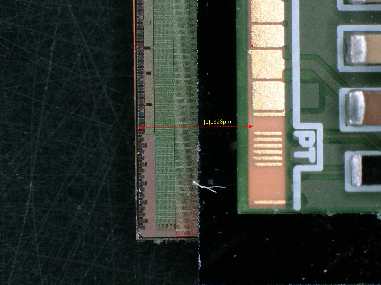
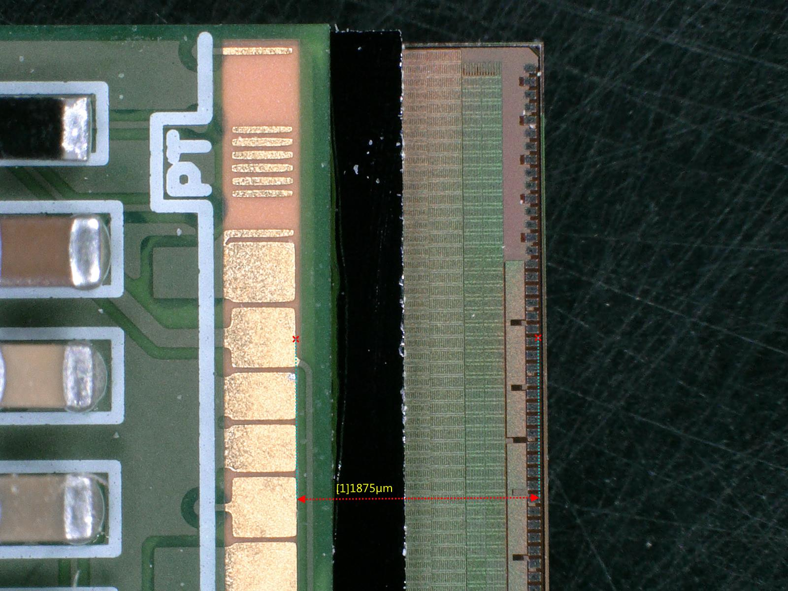
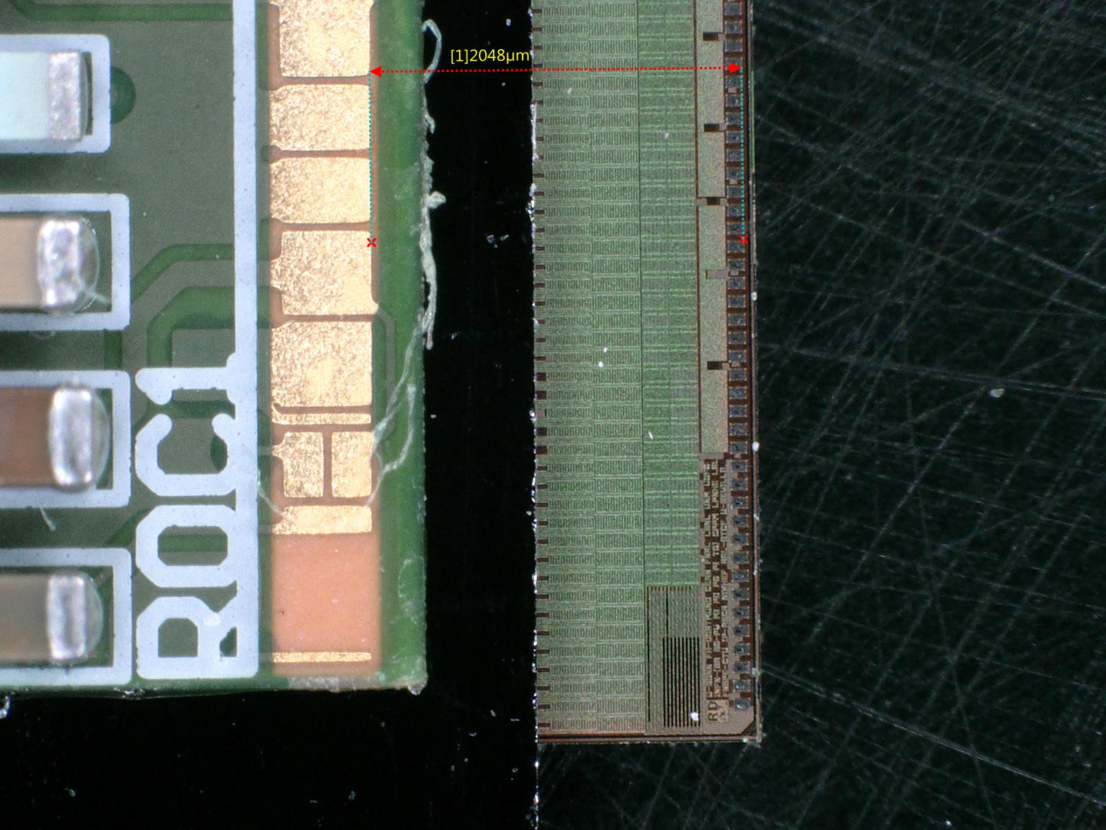
Measured the alignment of the two assembled module (one module was assembled during my last visit) using the microscope. The discrepancies in the distance between HDI wire-bond pads and ROC wire-bond pads are around 200 microns. If we take the length of the module to be 4cm, this is less than half a degree of tilt.
Worked on presentation reporting these activities for the tracker week. |
| Attachment 1: 1-1.jpg
|
|
| Attachment 2: 1-2.jpg
|
|
| Attachment 3: 1-3.jpg
|
|
| Attachment 4: 1-4.jpg
|
|
|
46
|
Mon Jan 20 18:09:50 2020 |
Matej Roguljic | General | Activities 20.-31.01.2020. | 20.01.
Expanded the HDI testing setup to be able to mount wire-bonded HDIs to HDI handles. Tested 12 HDIs (v7.2), all of them passed the tests. HDIs were given to Silvan and are located in the storage box in the assembly lab. They will be used for module production.
21.01.
Tested 4 HDIs, version 7.1. All passed the electrical tests.
Tested 16 v7.2 HDIs. All but one passed the electrical tests.
Glued a protection cap on a pre-production module (M1535).
22.01.
Investigated problems with full qualification setup, narrowed it down to communication between PC and Keithley.
23.01.
Tested 23 HDIs. One failed the test, rest of them passed.
24.01.
Tested 15 HDIs. All of them passed the tests.
Investigated problems with threshold/trim tests in full qualification when going to -20. Suspecting wrong DACs used in the test.
27.01.
Continuing to investigate problems with threshold in trimming procedures. The problem seems to be in the DAC 'ctrlreg' which was set to 17. Setting it to 9 removed the problem for M1529.
28.01.
Confirmed that 'ctrlreg' works also at room +20 degrees. Did reception test on modules 1529, 1536, 1537 and 1538. After this, caps were glued to modules 1537 and 1538. Did fulltest@-20, IV@-20, fullltest@+10 and IV@+10 for modules 1534, 1532, 1529 and 1536.
29.01.
Ran reeption on moules 1539 and 1540. Ran full qualification on modules 1536, 1537, 1538, 1540. Module 1539 turned out to have broken wirebonds on one TBM, reported this to Silvan and he re-bonded it. Assembled a second cap-gluing station. |
|
56
|
Mon Jan 27 17:50:48 2020 |
Matej Roguljic | Cold box tests | Failing modules at -20 | | Friday, 24.1., it was noticed that the modules are graded as 'C' in similar fashion. Module is graded A/B at +10 degrees and then graded C at -20. The reason for grade C was that the trimming procedure was not successful on at least one of the ROCs on each module. This problem was further investigated on 27.1. Wolfram suspected that the problem lies in zero suppression mode since the pixels with failed threshold comes in groups of four pixels. The corresponding DAC 'ctrlreg' was set, as recommended, to 17, during previous tests and after changing it to 9, the problems at -20 seem to be gone. This will be further investigated. |
|