| ID |
Date |
Author |
Category |
Subject |
|
129
|
Tue Mar 24 15:41:29 2020 |
Andrey Starodumov | Module grading | Change in MoreWeb GradingParameters.cfg |
On March 3d the Vcal calibration parameter has been changed:
- StandardVcal2ElectronConversionFactor from 50 to 44 (electrons/VCal)
Om March 24 the following changes done:
- trimThr from 35 to 50 (to synchronize with current target trimming threshold of Vcal=50)
- TrimBitDifference from 2. to -2. This means that difference between trimmed and untrimmed
threshold close to 0 (<2 as it was) will be ignored. |
|
142
|
Thu Mar 26 10:41:24 2020 |
danek kotlinski | Module grading | M1606 |
I have looked more closely at M1606.
Trimming show problems in ROC2, 8 pixels have 0 threshold and for 61 pixels thr=-1.
Strange because from Scurves the 61 have a high ~62 threshold but no failure.
The PixelAlive and PH is OK for these 61 pixels, the 8 are just completely dead.
Trimbit test shows that 61 pixels failing.
So maybe this is the first time we see a real trimbit failure!
I suggest to grate this module C+( or *). |
|
143
|
Thu Mar 26 15:37:18 2020 |
Urs | Module grading | M1606 |
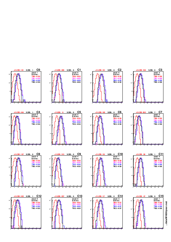
| attached find the threshold difference distributions for all four trimbits for all ROCs |
| Attachment 1: anaTrim-thrDiff-data__M1606__pxar.pdf
|
|
|
161
|
Tue Mar 31 06:54:12 2020 |
danek kotlinski | Module grading | M1542 |
I have tested M1542.
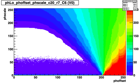
It looks not bad but there is a group of pixels in the lower/left corner of ROC6 which behave different.
One can also see that something is not right in some PH optimisation plots.
See the attached plot.
We should probably leave this module as grade C+.
D. |
| Attachment 1: Canvas_1.png
|
|
|
246
|
Fri May 1 19:34:01 2020 |
danek kotlinski | Module grading | M1582 |
M1582 was classified as C because of 167 pixels failing trimming in ROC1.
I have tested this module.
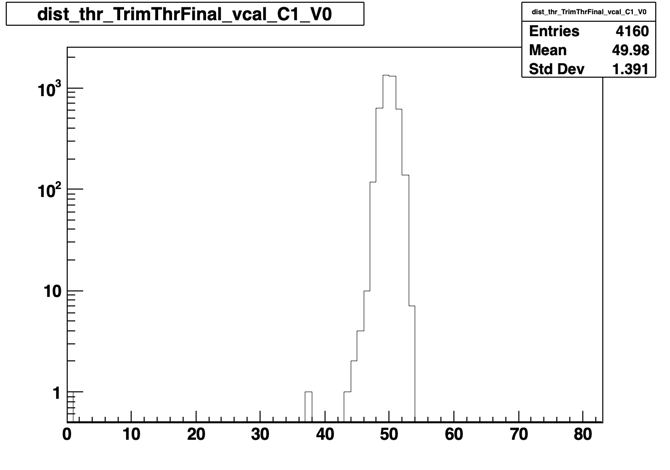
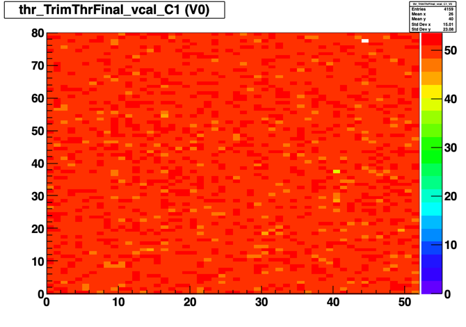
The attached plots show the 1d & 2d threshold distributions.
The average threshold is 49.98 with rms=1.39 there is 1 pixel failing (at 0) and 1 pixel with a very low threshold of 37.
I think this ROC is OK, actually it is very nice.
D. |
| Attachment 1: m1582_roc1_thr.png
|
|
| Attachment 2: m1582_roc1_thr_2d.png
|
|
|
254
|
Thu May 7 00:27:41 2020 |
Dinko Ferencek | Module grading | Comment about TrimBitDifference and its impact on the Trim Bit Test |
To expand on the following elog, on Mar. 24 Andrey changed the TrimBitDifference parameter in Analyse/Configuration/GradingParameters.cfg from 2 to -2
$ diff Analyse/Configuration/GradingParameters.cfg.default Analyse/Configuration/GradingParameters.cfg
45c45
< TrimBitDifference = 2.
---
> TrimBitDifference = -2.
From the way this parameter is used here, one can see from this line that setting the TrimBitDifference to any negative value effectively turns off the test.
More details about problems with the Trim Bit Test can be found in this elog. |
|
285
|
Fri Jun 5 13:47:11 2020 |
Andrey Starodumov | Module grading | M1613 |
| FT of this modules has been done twice: March 23 and March 25, in both cases with the final test SW. On March 23 module was graded C due to many trim bit failures. That is why it was retested. But after failure in trimbits were excluded from the grading, FT of Mar 23 looks better then later FT of Mar25. That is why FT of Mar 23 is kept. |
|
297
|
Fri Aug 28 11:13:33 2020 |
Andrey Starodumov | Module grading | M1615 |
M1615: one pixel in ROC10 unmaskable hence should be graded C. Otherwise the module is of grade A
To be checked! |
|
141
|
Wed Mar 25 20:17:16 2020 |
danek kotlinski | Module doctor | The list of modules tested today by Wolfram |
M1542 nothing on sdata3 (12-15), bad output or wire-bond
M1544 ROC15 timing off, can be made to work (roc 15 vdig 11, ..), but probably not usable for the detector
M1545 full readout, ok, upgraded to C*
M1546 TBM1 output alpha broken (sdata1) => replace TBM1
M1563 ROC 8 thinks he is roc 10 ==> check address wire bond on roc 8?
M1567 roc 11 missing, sdata2 (b-channel)
M1572 sticker says : both TBMs broken, no SDA => replace both TBMs?
M1593 tbm0, core B (roc 0-3), no decodable output, core/stack working ok, output beta+ high ~ 2V
M1594 roc 0 dead
M1615 nothing on sdata 3 (12-15), very bad cable (corrosion?) re-running with new cable
M1616 ROC 10 not programmable, no roc headers on sdata2 (b) ==> TODO check clock to roc 10
M1617 readout but no hits in ROC 8, mechanical damage on chip edge
M1621 ROC 8 not programmable, no roc headers or tbm trailers on sdata2a (tbm1b) ==> TODO check clock on ROC 8
M1623 probably no cal-trig-reset to roc 0-3
M1625 definitely not cal-trig-reset to roc 0-3 (CTR- at 0V), damaged when trying to pull wire-bonds
M1575 no readout from rocs 0,1 (tbm0b, sdata4), all rocs programmable ==> TODO check CTR roc 0 |
|
150
|
Fri Mar 27 14:46:04 2020 |
Andrey Starodumov | Module doctor | Wolfram's summay from Mar 25 |
M1542 nothing on sdata3 (12-15), bad output or wire-bond
M1544 ROC15 timing off, can be made to work (roc 15 vdig 11, ..), but probably not usable for the detector
M1545 full readout, ok, upgraded to C*
M1546 TBM1 output alpha broken (sdata1) => replace TBM1
M1563 ROC 8 thinks he is roc 10 ==> check address wire bond on roc 8?
M1567 roc 11 missing, sdata2 (b-channel)
M1572 sticker says : both TBMs broken, no SDA => replace both TBMs?
M1575 no readout from rocs 0,1 (tbm0b, sdata4), all rocs programmable ==> TODO check CTR roc 0
M1593 tbm0, core B (roc 0-3), no decodable output, core/stack working ok, output beta+ high ~ 2V
M1594 roc 0 dead
M1615 nothing on sdata 3 (12-15), very bad cable (corrosion?) re-running with new cable
M1616 ROC 10 not programmable, no roc headers on sdata2 (b) ==> TODO check clock to roc 10
M1617 readout but no hits in ROC 8, mechanical damage on chip edge
M1621 ROC 8 not programmable, no roc headers or tbm trailers on sdata2a (tbm1b) ==> TODO check clock on ROC 8
M1623 probably no cal-trig-reset to roc 0-3
M1625 definitely not cal-trig-reset to roc 0-3 (CTR- at 0V), damaged when trying to pull wire-bonds |
|
151
|
Fri Mar 27 16:41:16 2020 |
Andrey Starodumov | Module doctor | Wolfram's summay from Mar 25 |
| Andrey Starodumov wrote: | M1542 nothing on sdata3 (12-15), bad output or wire-bond
M1544 ROC15 timing off, can be made to work (roc 15 vdig 11, ..), but probably not usable for the detector
M1545 full readout, ok, upgraded to C*
M1546 TBM1 output alpha broken (sdata1) => replace TBM1
M1563 ROC 8 thinks he is roc 10 ==> check address wire bond on roc 8?
M1567 roc 11 missing, sdata2 (b-channel)
M1572 sticker says : both TBMs broken, no SDA => replace both TBMs?
M1575 no readout from rocs 0,1 (tbm0b, sdata4), all rocs programmable ==> TODO check CTR roc 0
M1593 tbm0, core B (roc 0-3), no decodable output, core/stack working ok, output beta+ high ~ 2V
M1594 roc 0 dead
M1615 nothing on sdata 3 (12-15), very bad cable (corrosion?) re-running with new cable
M1616 ROC 10 not programmable, no roc headers on sdata2 (b) ==> TODO check clock to roc 10
M1617 readout but no hits in ROC 8, mechanical damage on chip edge
M1621 ROC 8 not programmable, no roc headers or tbm trailers on sdata2a (tbm1b) ==> TODO check clock on ROC 8
M1623 probably no cal-trig-reset to roc 0-3
M1625 definitely not cal-trig-reset to roc 0-3 (CTR- at 0V), damaged when trying to pull wire-bonds |
M1542 is fully OK. It's graded C due to very broad relative Gain distribution of ROC6.
If we will have time it would be useful to take a close look at this module.
It remains graded C. |
|
183
|
Fri Apr 3 17:39:19 2020 |
Andrey Starodumov | Module doctor | M1654 |
After a protection cap glued to M1654, I observed a few strongly bent wire bonds and probably some shorts on ROC8. One (VD+) of them is even detached (on HDI side). Pads from 25/26 till 35 are affected.
Nevertheless the Reception test gave the same results as before the cap gluing: grade A.
It would be useful if Wolfram take a look and decide what to do. Silvan proposed to remove cap and repair wire-bonds.
I could test the procedure on a dummy module (I have one) with glued cap and, if successful, do the same with M1654.
For the moment the module is placed in Module doctor tray. |
|
213
|
Wed Apr 15 08:48:09 2020 |
danek kotlinski | Module doctor | Wolfram's tests from 14/4/20 |
two of are fixed and can be re-tested
M1623 tbm bond
M1657 bond roc 15
the others need further investigation, maybe a new tbm, maybe closer wire-bond inspection
M1633 roc 0-3 programmable, but no readout, unclear
M1635 roc 12-15 programmable, but no readout (except for roc 12), no token passed
M1653 roc 12-15 not programmable, otherwise ok, sda? tbm?
M1671 some problem with roc 14/15, unclear |
|
5
|
Wed Aug 7 11:49:07 2019 |
Matej Roguljic | Module assembly | HDI glue irradiation tests |
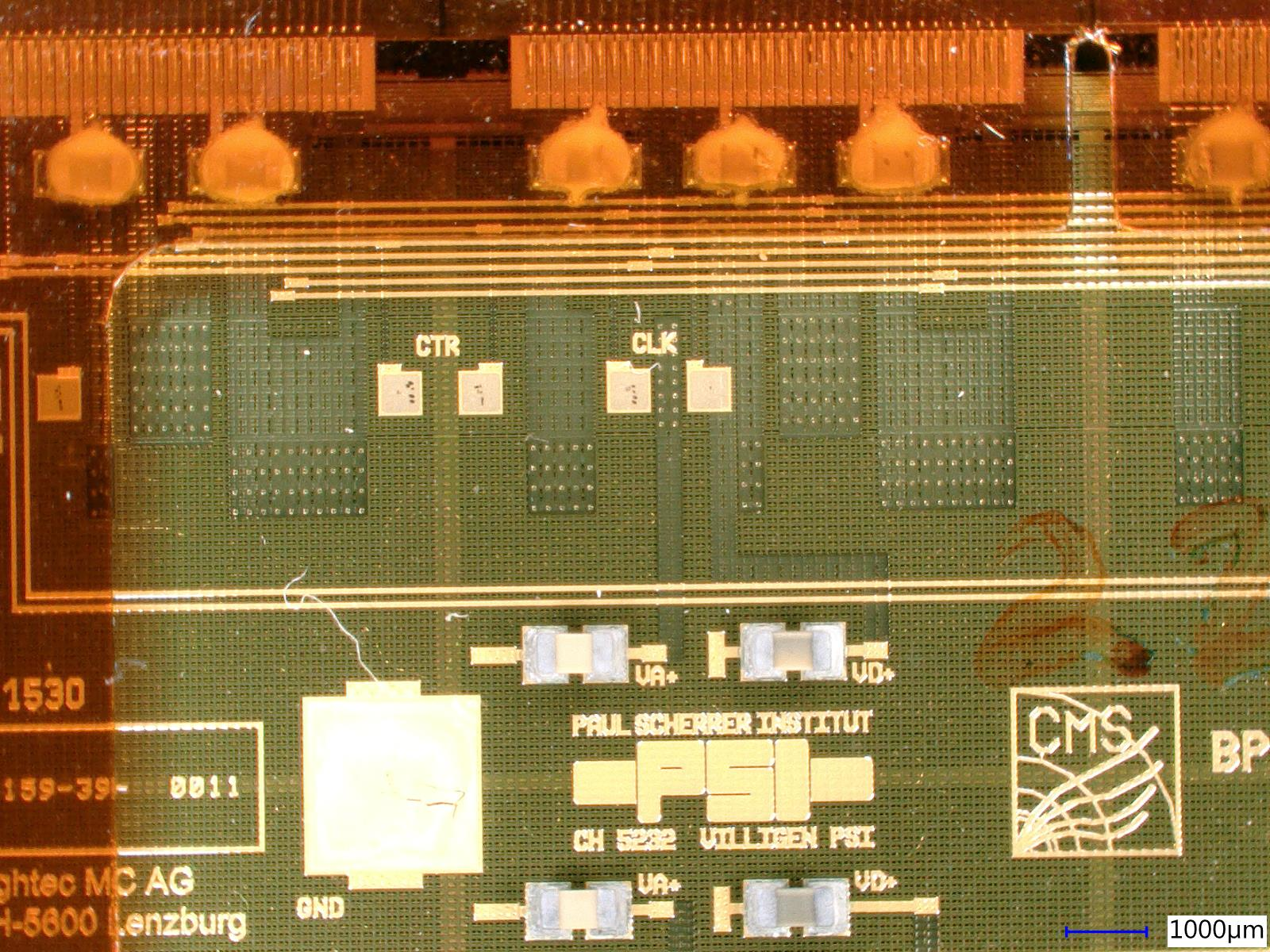
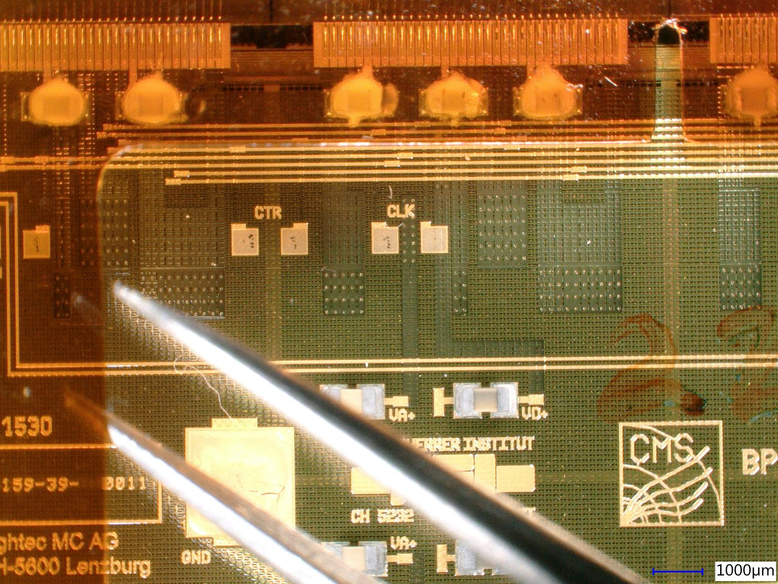
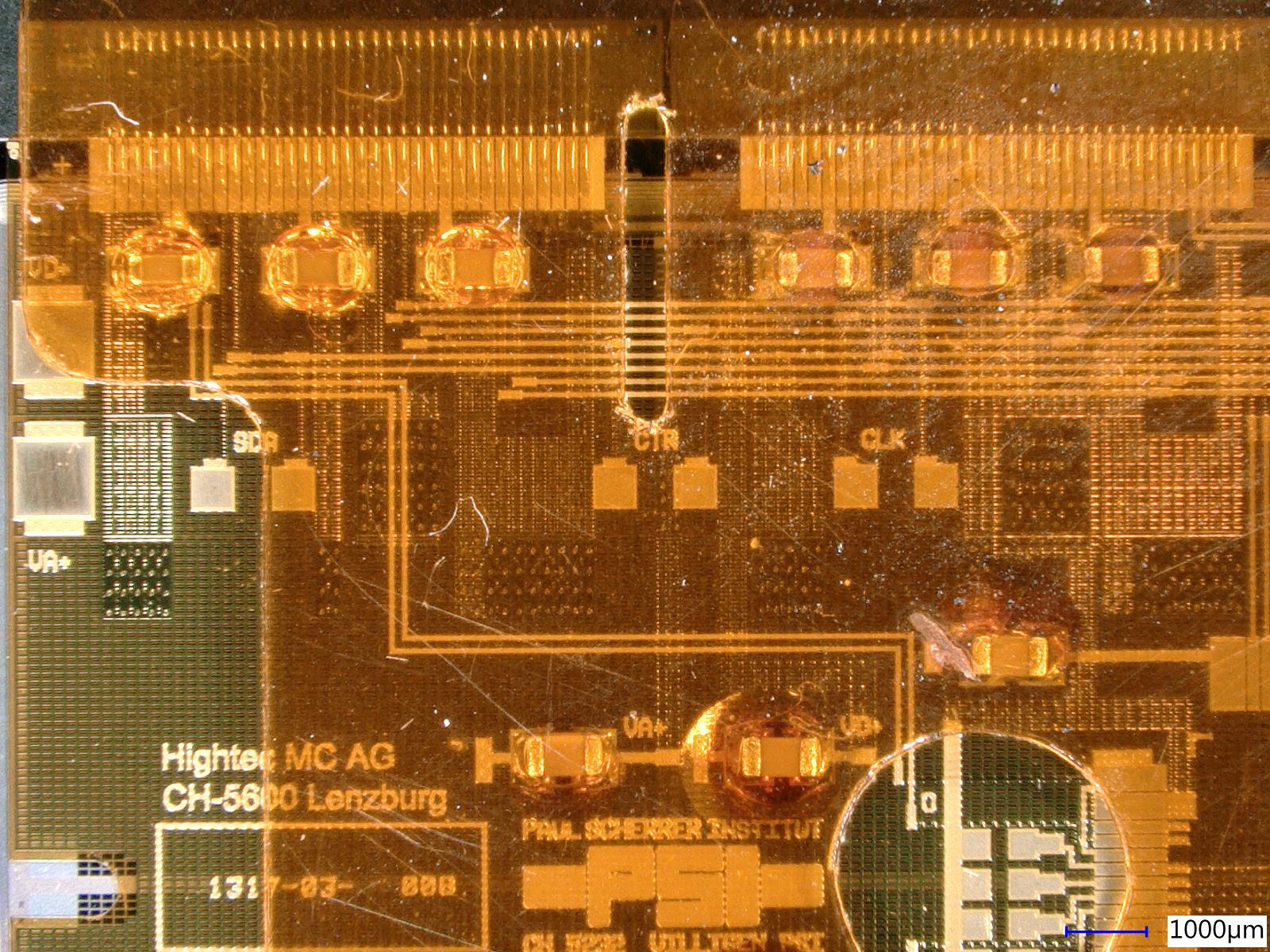
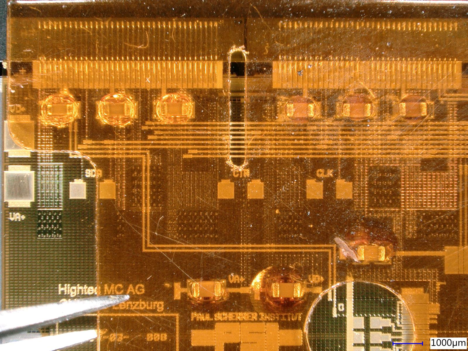
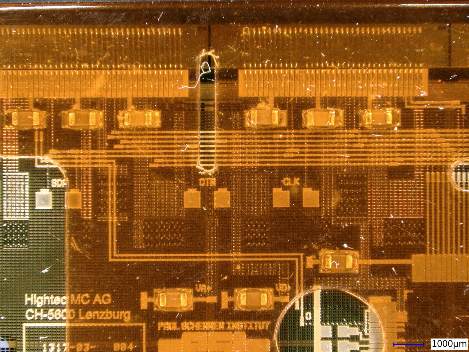
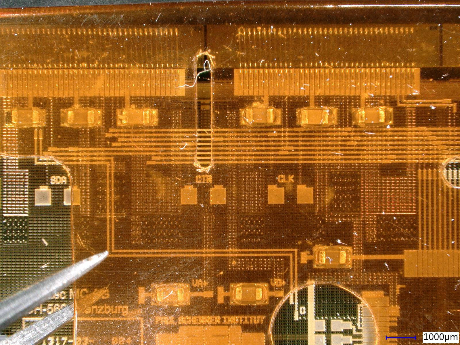
Six different glues were used to glue the cap on six dummy modules. They were all irradiated to 120 MRad in Zagreb after which they were taken to PSI and tested with the tweezers under the microscope.
Standard glue (Dow-cornig), used in CMS - it became "two-component". Solid part on the capacitors and the liquid part on the cap. Surface tension was actually holding the cap quite strongly. Silvan deemed it the second best glue
Two component epoxy adhesive - the strongest glue out of all tested. The only drawback of it was that during the application of the glue to the capacitors, it left puddles around some of them since it is quite liquid before curing. This might have been prevented if we had a proper glue stamp. The glue stamp used at the time contained too much excess glue, and if another one was printed, with small grooves where the capacitors are, the amount of glue transferred should be lower and no puddles should appear. This glue was graded the best of all the tested glues. EDIT: the glue stamp with smaller grooves was printed and now there are no puddles anymore.
SG-20 (black) - sticks, but not really well. It was also quite soft and malleable. Because it doesn't stick very well, it is not recommended for gluing the cap.
WS-200 - almost identical to the SG-20, just a different color.
Terosan MS939 - doesn't stick, not recommended.
Ergo 6521 - doesn't stick, not recommended.
Took photos of them under the microscope. There are two photos for each glue. First one is while the cap is at rest, while on the second there is an upwards force applied with the tweezers. All of them except the two component epoxy adhesive detached when force was applied. With the epoxy adehsive, the module started lifting, but the glue held. |
| Attachment 1: dowCornig_con.jpg
|
|
| Attachment 2: dowCornig_split.jpg
|
|
| Attachment 3: epoxy_2component_con.jpg
|
|
| Attachment 4: epoxy_2component_split.jpg
|
|
| Attachment 5: sg20_con.jpg
|
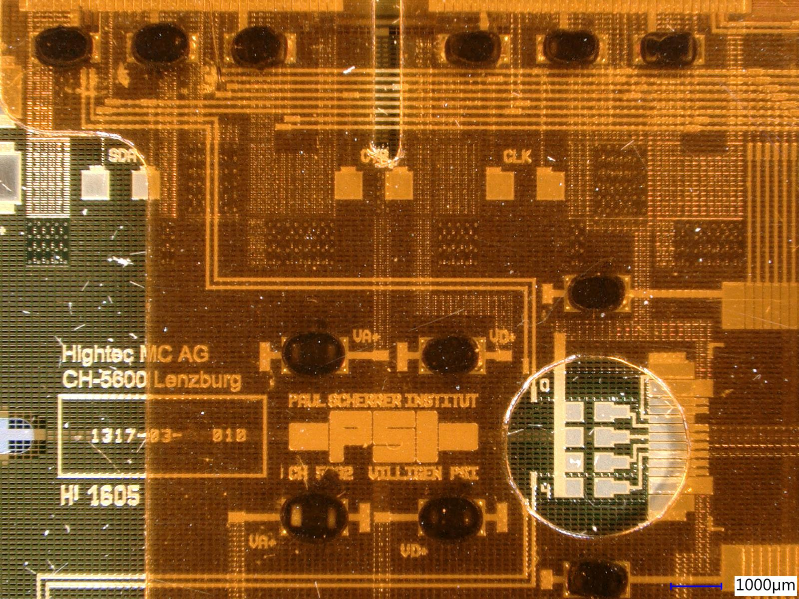
|
| Attachment 6: sg20_split.jpg
|
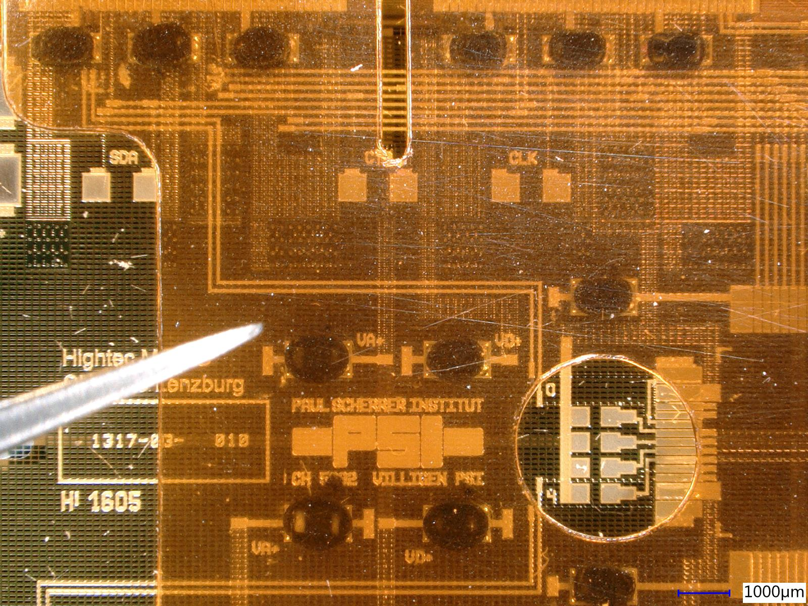
|
| Attachment 7: terosan_ms939_con.jpg
|
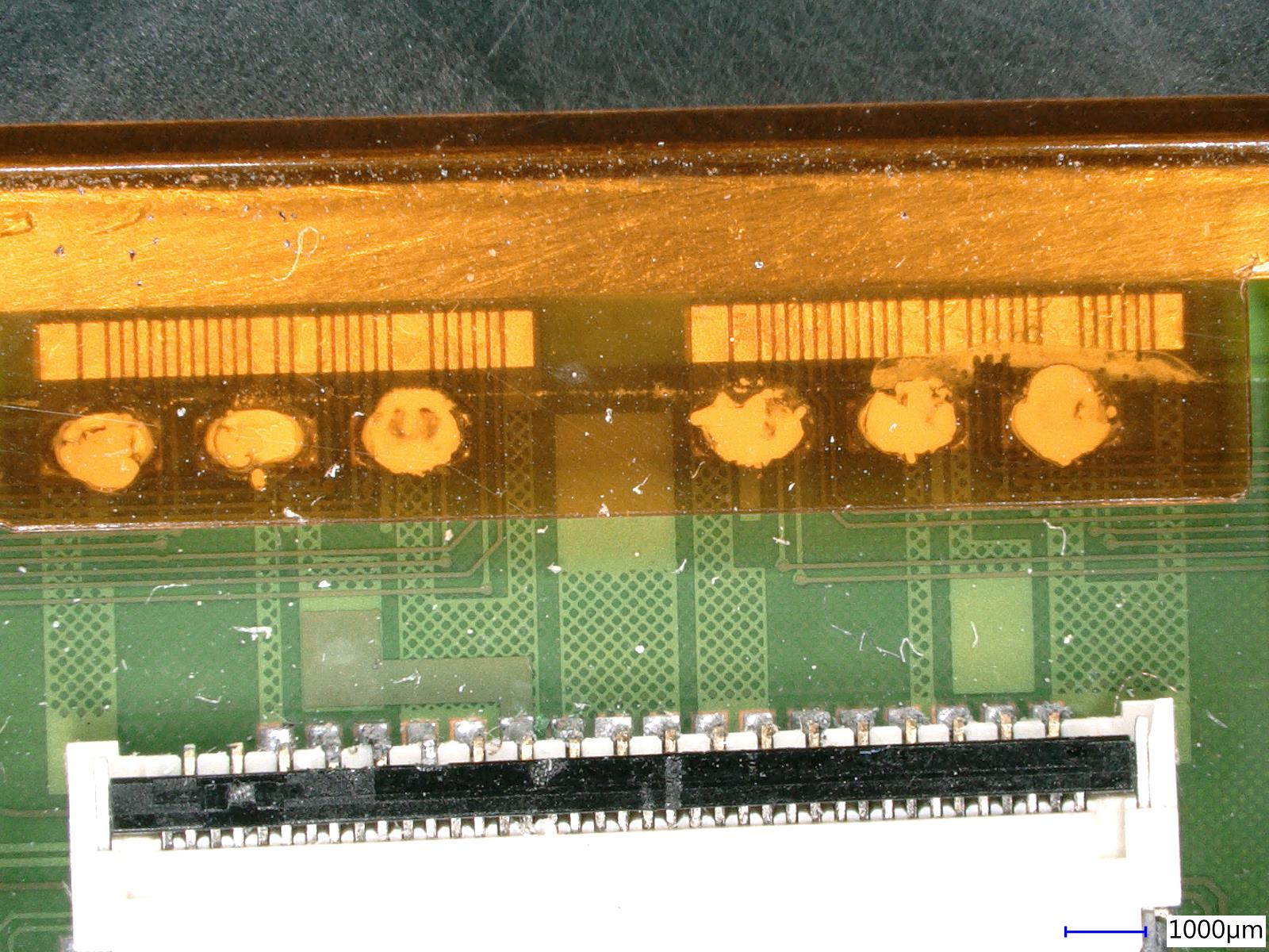
|
| Attachment 8: terosan_ms939_split.jpg
|
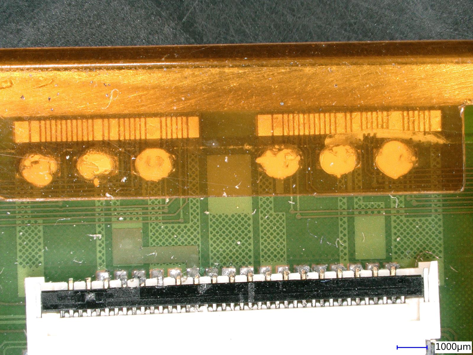
|
| Attachment 9: ws200_con.jpg
|
|
| Attachment 10: ws200_split.jpg
|
|
|
11
|
Wed Sep 18 15:45:45 2019 |
Matej Roguljic | Module assembly | HDI sparking under HV test |
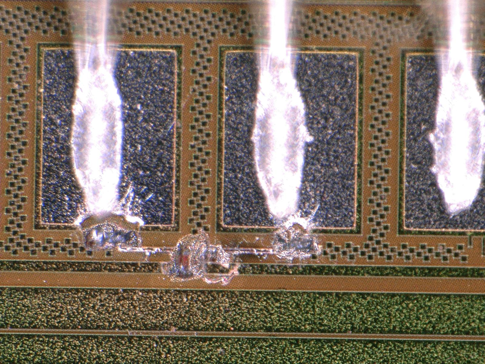
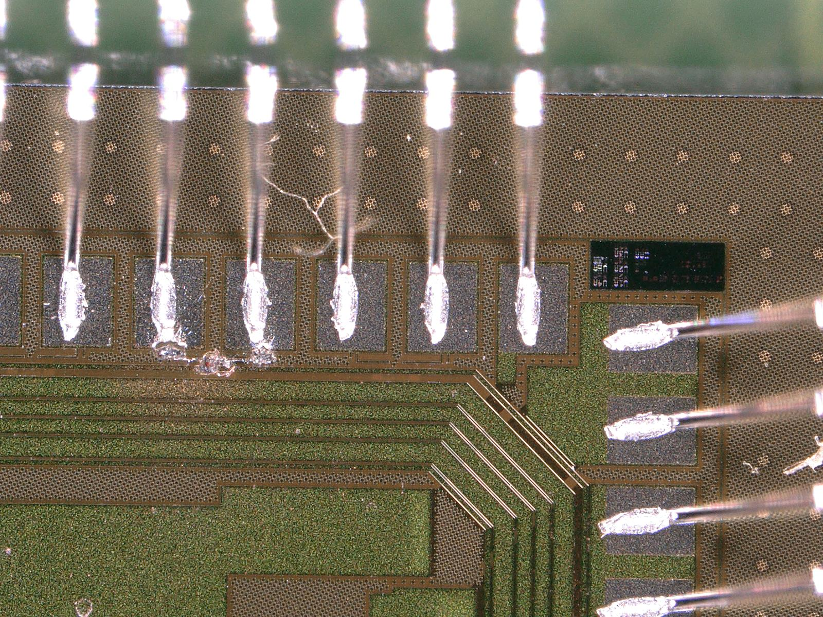
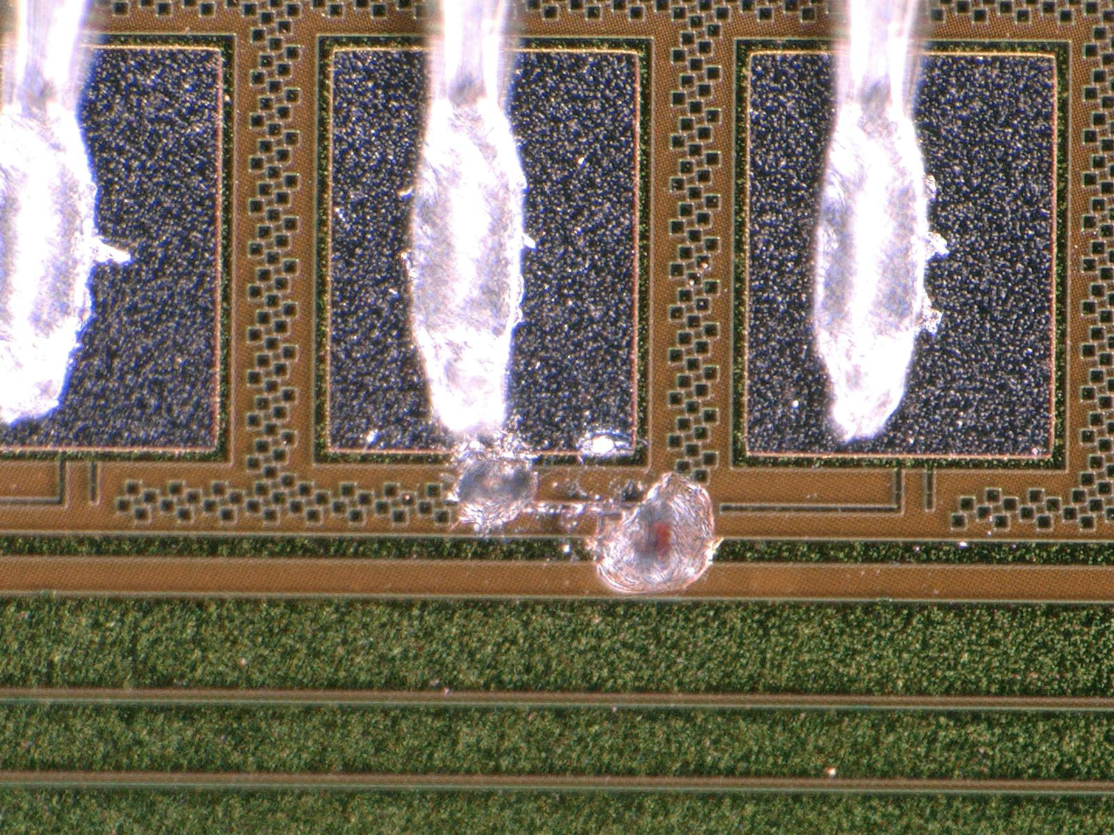
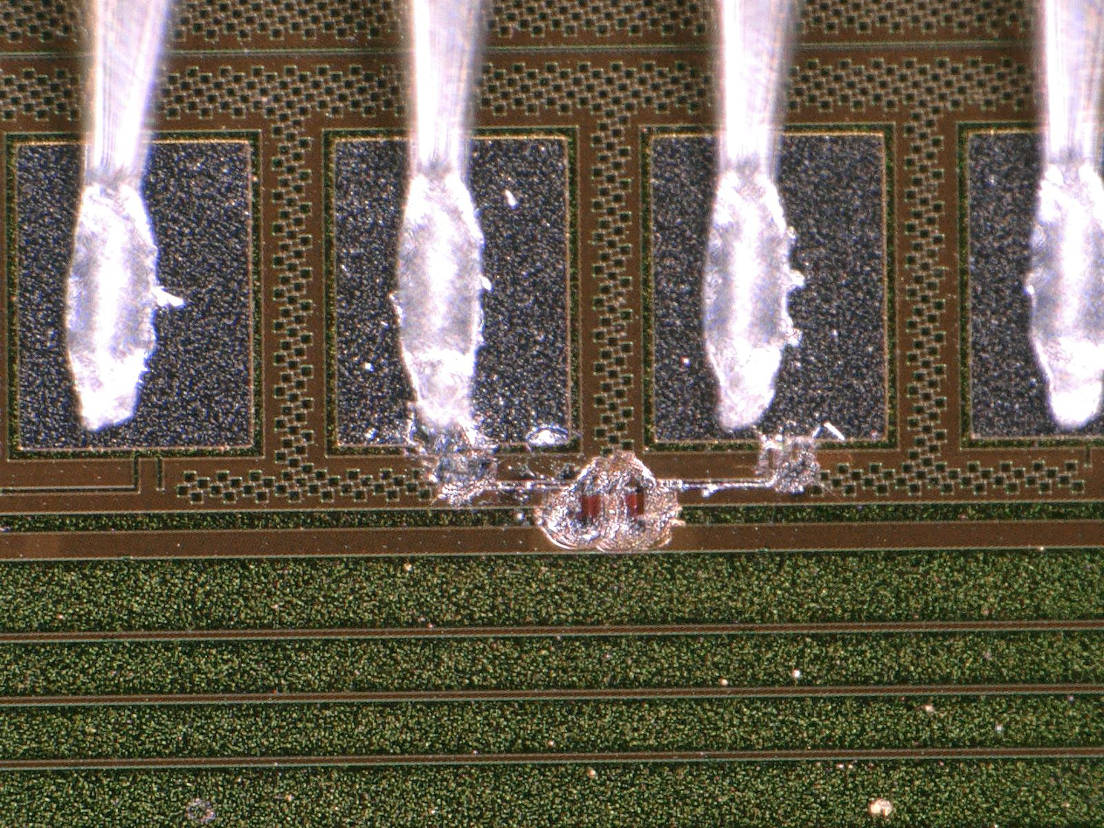
HDI 8010 passed all test except the HV. Under the HV test, some sparks could be heard and even seen by eye on the right TBM (closer to the HV pad!). Testing it again, showed that it was indeed damaged by the spark. Sparking craters could be seen with the microscope between pads 4 and 5 of the TBM.
The same thing happened a month later, on HDI 8012. Again, it passed all the test until HV when sparks appeared and damaged the TBM, and, curiously enough, the damage was on the same position on the TBM as with 8010.
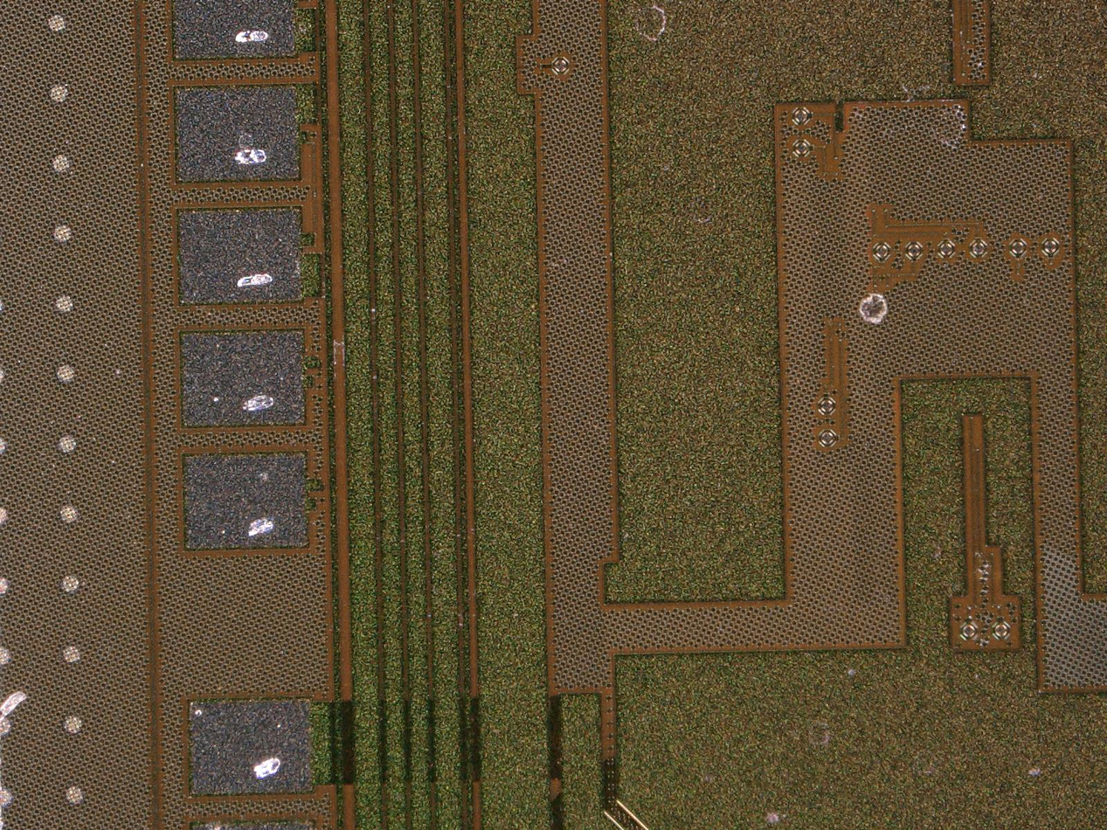
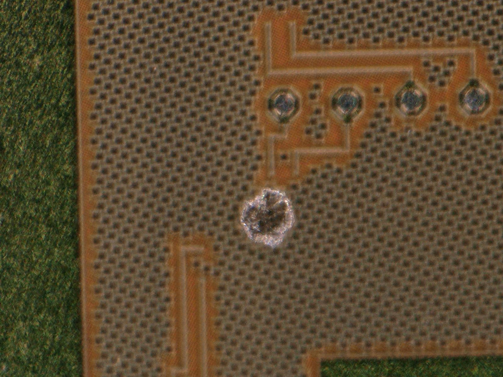
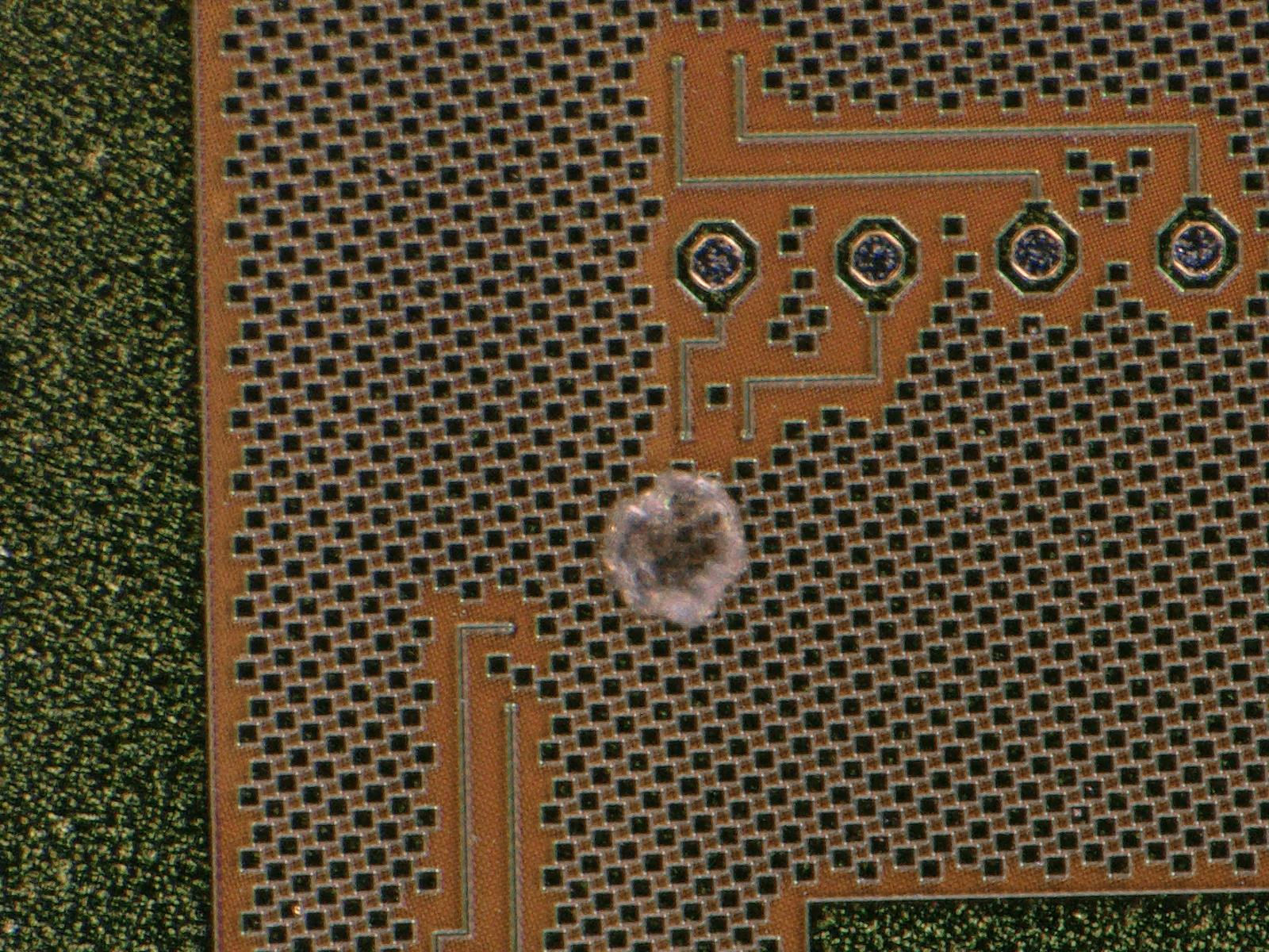
HDI 8011 was put under the HV test as well, however, this one didn't have any wires bonded to the TBMs because gold plating was missing on several of the wire bonds. Sparking could be heard, but we couldn't located where the damage happened. There is one potential candidate, shown on the photo attached to this log entry.
On 18.09. a possible explanation for the sparking was thought of. Wolfram and Matej put one of the "faulty" HDIs under HV test and noticed that sometimes a spark could be seen between the HDI handle and the aluminum base plate! It looks like the HV pin rests near the border of the HV pad and the ending of the HDI. Because of that, there is a discharge from the HV pin to the HDI handle. The discharge connects to the ROC wire bond pads closest to the HV pad providing a way to affect the TBM! This is further strengthened by the fact that the damaged TBM pad is connected to the first four ROCs closest to the HV pad. To test this, we put kapton tape on the HDI handle, near the HV pad and tested the HDI again and there were no sparks.
The HDIs to be used for L1 replacement are slightly longer to prevent HV jumping to the sensor. Incidentally, this might also solve the sparking issue. If the issue is not solved on the longer HDIs, HDI holders will have to be further isolated in the region close to the HV pad. |
| Attachment 1: HDI_8010.jpg
|
|
| Attachment 2: HDI_8010_unzoom.jpg
|
|
| Attachment 3: HDI_8012.jpg
|
|
| Attachment 4: HDI_8012_2.jpg
|
|
| Attachment 5: HDI_8011_1.jpg
|
|
| Attachment 6: HDI_8011_2.jpg
|
|
| Attachment 7: HDI_8011_3.jpg
|
|
|
16
|
Thu Sep 26 21:48:56 2019 |
Dinko Ferencek | Module assembly | Cap gluing training |
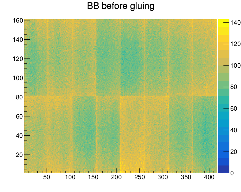
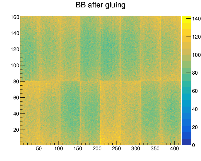
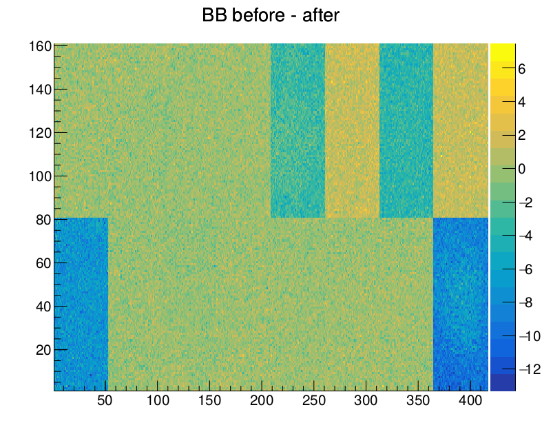
| Today I performed my first cap gluing. As an exercise it was first done on two dummy modules and later on a pre-production module M1522. Before the cap gluing the module M1522 was visually inspected and a Reception test was run. Before the cap gluing everything looked fine. After the cap gluing the module M15222 was again visually inspected and it looked like wire bonds in one of the corners might have been slightly bent and some glue got deposited on some of the wire bonds. The Reception test will be repeated tomorrow. |
|
19
|
Fri Sep 27 23:22:02 2019 |
Dinko Ferencek | Module assembly | Cap gluing training |
| Attached are the bump bonding threshold maps before and after cap gluing and the (before - after) difference for M1522. |
| Attachment 1: M1522_beforeGluing.png
|
|
| Attachment 2: M1522_afterGluing.png
|
|
| Attachment 3: M1522_diff.png
|
|
|
20
|
Wed Oct 2 12:41:16 2019 |
Dinko Ferencek | Module assembly | First production modules assembled |
First production modules (M1530, M1531, M1532) were built on Monday, Sep. 30 2019.
There was a problem with wire bonding of ROC5 on M1530. There is a small crater on one of the ROC pads which appears to had been created by the BareModule probe card needle.
After initial tests with pXar of the 3 modules, noticed the following:
M1530: data missing from ROCs 4 and 5 (expected based on the wire bond problem on ROC5) but otherwise looks fine
M1531: could set Vana but setvthrcompcaldel and pixelalive not showing any data
M1532: looks fine.
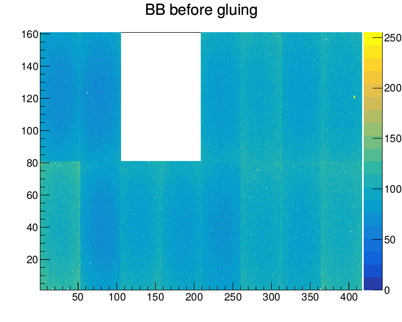
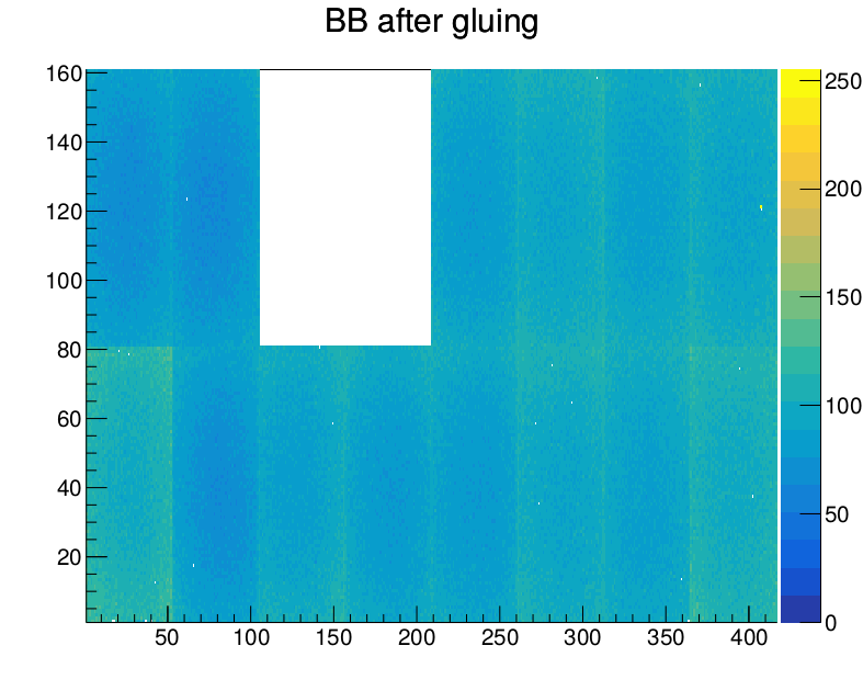
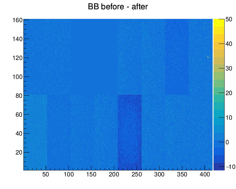
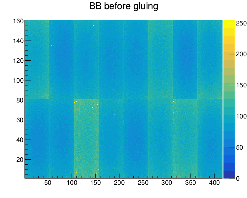
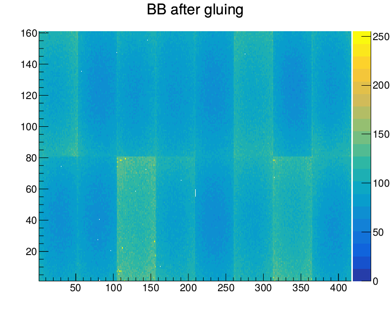
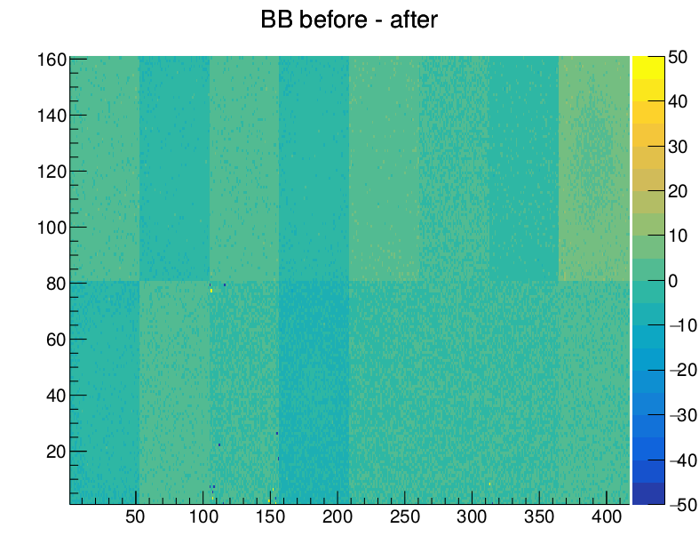
Caps were glued to M1530 and M1532 (damaged cap was glued to M1530) and Reception tests were run before and after gluing. Attached are the bump bonding threshold maps before and after cap gluing and the (before - after) difference for M1530 and M1532. |
| Attachment 1: M1530_beforeGluing.png
|
|
| Attachment 2: M1530_afterGluing.png
|
|
| Attachment 3: M1530_diff.png
|
|
| Attachment 4: M1532_beforeGluing.png
|
|
| Attachment 5: M1532_afterGluing.png
|
|
| Attachment 6: M1532_diff.png
|
|
|
25
|
Tue Oct 29 16:36:23 2019 |
Matej Roguljic | Module assembly | Assembly lab cap gluing jigs |
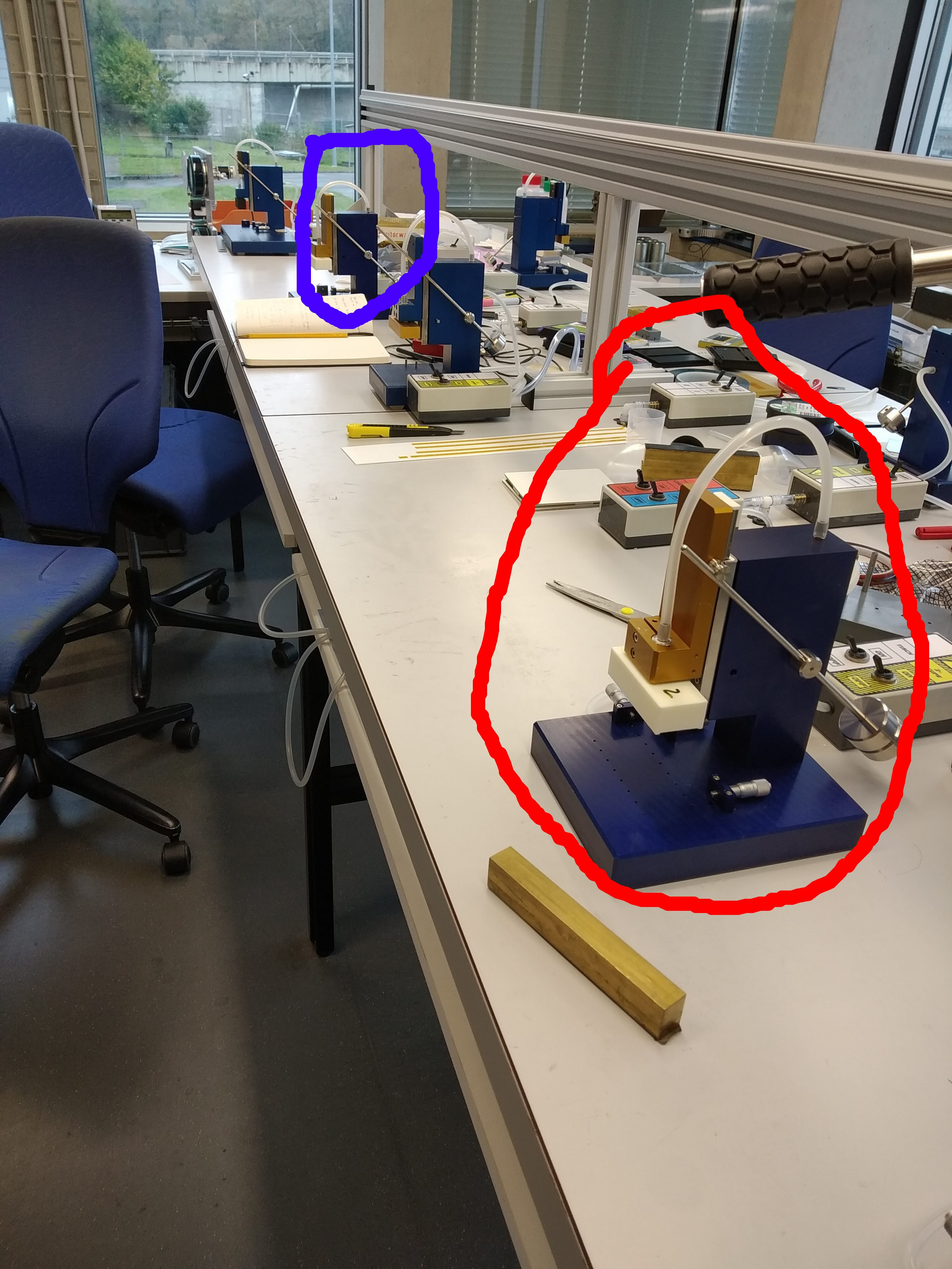
There are two jigs for cap gluing in the assembly lab, circled in red and blue on the photo in the attachment. The one closer to the door (red) we used to build glue Phase 2 HDI to a dummy sensor and four Phase2 ROCs. Before changing the head, the numbers of the alignment screws were noted.
The jig closer to the doors (red): Top two pins - 5.75; Left pin - 5.5
The jig further from the doors (blue): Top two pins - 5.71, Left pin - 3.25 |
| Attachment 1: IMG_20191029_150037.jpg
|
|
|
54
|
Fri Jan 24 18:16:09 2020 |
Dinko Ferencek | Module assembly | Protective cap gluing |
| Today I additionally practiced protective cap gluing by adding a protective cap to module M1536. |