| ID |
Date |
Author |
Category |
Subject |
|
57
|
Thu Jan 30 13:51:03 2020 |
Matej Roguljic | Cold box tests | Fulltest failure - psiAgente |
During the first fulltest@-20 of the full qualification procedure for modules: 1539, 1541, 1542 and 1543; an error message popped up "psi Agente: self.Testboards[0] failed - the following boards are busy: TB1(DTB...:M1541), TB2(DTB...:M1542), TB3(DTB...:M1543). This means that the first fulltest for module 1539 was not executed.
Second fulltest seems to be working fine (so far)
Cause of this problem is not clear. |
|
101
|
Wed Mar 11 17:12:05 2020 |
Matej Roguljic | HDI test | HDI testing procedure change |
There is an additional test that will be used from 11.03. on all HDIs. It involves measuring the voltage between ground and the HV pin of the needle card with the goal of checking whether proper voltage is delivered to the HDI. The HDI testing script has been updated and it now prompts the user to set the voltage to -800 V, measure the voltage on the pin and write this into the test results. After this, another instruction has been added which tells the user to raise the Z-stage (needle card) before setting voltage to -1100 V. This is done to prevent sparking from the HV pad to the HV pin if the alignment is slightly off.
While measuring the voltage on the HV pin, one should keep in mind the proper settings on the Keithley. When the voltmeter probe is connected to the pin, the current reading on Keithley will go up and if the current readout range is low, it will limit the voltage even before hitting compliance. This was observed during the initial testing of the new procedure. Range should be set to maximum (100 muA) and compliance should be set to 105 muA. This is high enough that it is not reached while measuring voltage at -800 V. |
|
102
|
Wed Mar 11 17:22:57 2020 |
Matej Roguljic | HDI test | 8 HDI tests on 11.3. |
I tested 8 HDIs today: 5029,5030,5031,6034,6036,6035,1031 and 1032
All of them tested fine. |
|
104
|
Thu Mar 12 12:19:43 2020 |
Matej Roguljic | HDI test | 5 HDI tests on 12.3. |
| I tested 5 HDIs on 12.3. 1030,1029,1040,1039 and 1038. 1039 failed all the electrical tests. All the others passed the tests. HDI 1038 has one wirebond which is connected to the pad on the HDI and then it extends back up (like this: TBM./\.HDI/). The connection is good, but I just want to check with Silvan later if this is a problem. |
|
105
|
Thu Mar 12 17:21:59 2020 |
Matej Roguljic | Full test | Fulltests on 2020/03/12 |
Modules tested:
M1557 C (trim bits at -20)
M1558 C (gain at -20)
M1590 B (still graded C in moreweb because of the previous full qualification, this should be corrected)
M1600 B (still graded C in moreweb because of the previous full qualification, this should be corrected) |
|
107
|
Sat Mar 14 17:08:14 2020 |
Matej Roguljic | Full test | Fulltests on 2020/03/13 |
Modules tested:
M1591 C (gain at -20)
M1595 B
M1597 B
M1598 B |
|
108
|
Mon Mar 16 10:05:23 2020 |
Matej Roguljic | Software | PhQualification change |
| Urs made a change in pXar, in the PhOptimization algorithm. One of the changes is in the testParameters.dat where vcalhigh is set to 100 instead of 255. This was implemented on the PC used to run full qualification. A separate procedure for elComandante was created, "PhQualification.ini", which runs pretest, pixelalive, trimming, ph and gainpedestal. This procedure will need to be run on all the modules qualified before this change was made and later merged with previous full qualification results. |
|
109
|
Mon Mar 16 11:04:41 2020 |
Matej Roguljic | PhQualification | PhQualification 14.-15.3. |
I ran PhQualification over the weekend with changes pulled from git (described here https://elrond.irb.hr/elog/Layer+1+Replacement/108).
14.3. M1554, M1555, M1556, M1557
First run included software changes, but I forgot to change the vcalhigh in testParameters.dat
The summary can be seen in ~/L1_SW/pxar/ana/T-20/VcalHigh255 (change T-20 to T+10 to see results for +10 degrees)
Second run was with vcalhigh 100.
The summary can be seen in ~/L1_SW/pxar/ana/T-20/Vcal100
15.3. M1558, M1559, M1560
I only ran 3 modules because DTB2 (WRE1O5) or its adapter was not working. Summary is in ~/L1_SW/pxar/ana/T-20/Vcal100
The full data from the tests are in ~/L1_DATA/MXXXX_PhQualification_... |
|
110
|
Mon Mar 16 15:17:18 2020 |
Matej Roguljic | Module assembly | M1601 and M1602 |
| Andrey and I assembled modules 1601 and 1602 on Friday, 13.3. On Monday, 16.3. I ran reception on them (both graded A) and then glued protection caps on them. |
|
111
|
Mon Mar 16 15:20:03 2020 |
Matej Roguljic | PhQualification | PhQualification on 16.3. |
| PhQualification was run on modules M1561, M1564, M1565, M1566. |
|
243
|
Thu Apr 30 16:47:00 2020 |
Matej Roguljic | Software | MoReWeb empty DAC plots |
Some of the DAC parameters plots were empty in the total production overview page. All the empty plots had the number "35" in them (e.g. DAC distribution m20_1 vana 35). The problem was tracked down to the trimming configuration. Moreweb was expecting us to trim to Vcal 35, while we decided to trim to Vcal 50. I "grepped" where this was hardcoded and changed 35->50.
The places where I made changes:
- Analyse/AbstractClasses/TestResultEnvironment.py
'trimThr':35
- Analyse/Configuration/GradingParameters.cfg.default
trimThr = 35
- Analyse/OverviewClasses/CMSPixel/ProductionOverview/ProductionOverviewPage/ProductionOverviewPage.py
TrimThresholds = ['', '35']
- Analyse/OverviewClasses/CMSPixel/ProductionOverview/ProductionOverviewPage/ProductionOverviewPage.py
self.SubPages.append({"InitialAttributes" : {"Anchor": "DACDSpread35", "Title": "DAC parameter spread per module - 35"}, "Key": "Section","Module": "Section"})
It's interesting to note that someone had already made the change in "Analyse/Configuration/GradingParameters.cfg" |
|
301
|
Wed Sep 2 16:09:24 2020 |
Matej Roguljic | Modules for P | M1595 switch with M1558 |
| Module 1595 was foreseen to go on the inner ladder 5, position -2 (negative two). During the pre-installation test, we saw it had a high leakage current, ~8 microAmps at room temperature. Therefore, we decided to place module 1558 in its place instead of it. |
|
1
|
Tue Aug 6 14:30:00 2019 |
Dinko Ferencek | Documentation | Jumo Imago 500 manuals |
| Manuals can be found at https://www.manualslib.com/products/Jumo-Imago-500-8786441.html |
|
12
|
Thu Sep 19 00:52:24 2019 |
Dinko Ferencek | Other | Modules 1504, 1505, 1520 irradiation report |
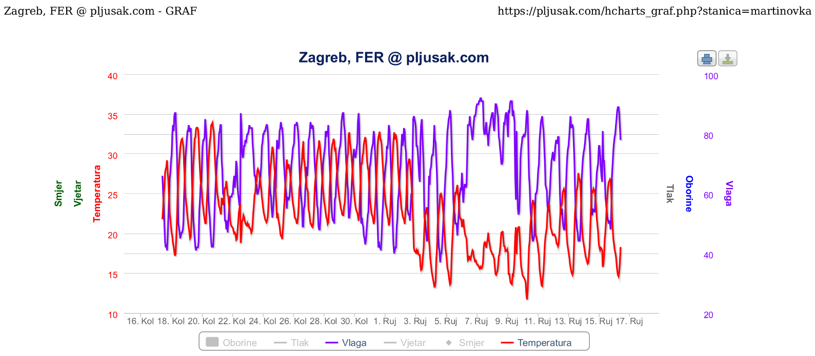
| Andrey Starodumov wrote: | It was discovered that these modules were stored in Zagreb in the climatic lab where T was about +22C. These modules have been transported from Co60 irradiation facility to the lab on open air with T>30C and RH>70%. Water in the air under the cap condensated on the surface of HDIs and diluted residuals (from soldering, passivation etc), that after remains liquid or crystallised.
The irradiation itself does not course any damage. This is also confirmed by the fact that after two previous irradiations in Jan and Jul 2019 of modules and HDIs, samples remained in a good shape without any residuals on HSI surfaces. These samples have been kept in an office where T and RH were similar to the outside and not in the climatic lab.
We consider the the case is understood and closed. |
Just to clarify. The modules were not transported from Co60 the irradiation facility to the lab in open air but inside a closed Petri dish. Otherwise, there would be no risk of water condensation if the air surrounding modules was allowed to quickly mix with the air-conditioned lab air. Here the problem arose from the fact that it was not only the modules that were brought inside the lab but they were brought inside a pocket of the outside air. A closed Petri dish is not airtight but it significantly reduces mixing of the air inside the Petri dish with the surrounding lab air making it slower than the rate at which the Petri dish and the module inside it were cooling down once brought inside the lab. This could have led to water condensation if the pocket of air trapped inside the Petri dish was warm and humid and had a dew point above the lab air temperature. To prevent this from happening, the solution should be relatively simple and it would be to open the Petri dish and uncover modules before bringing them inside the lab. That way the exchange of air will be faster and the risk of condensation will be basically gone because a warm module will be quickly surrounded by the lab air which will not condense on a warmer surface.
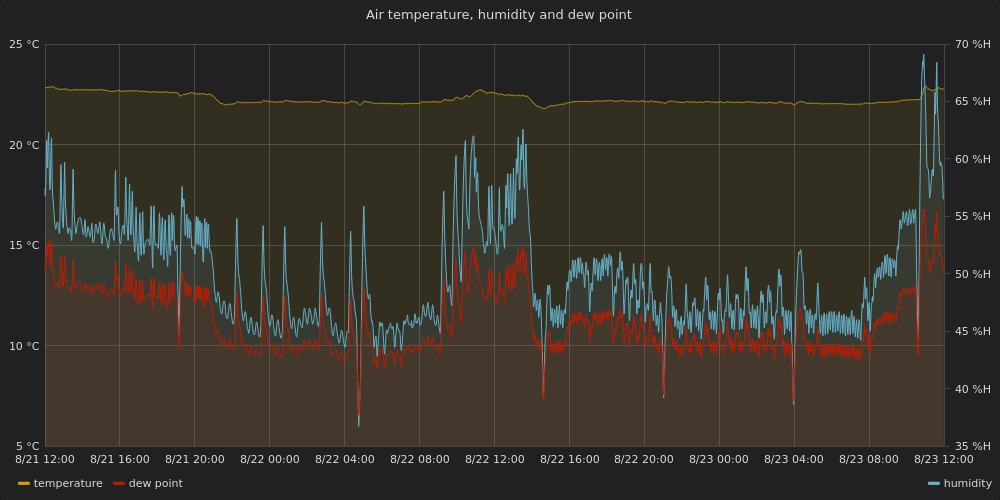
However, there is an additional twist in this particular case. On Aug. 22, when the modules were brought in the lab, there was a thunderstorm in Zagreb in the early afternoon (https://www.zagreb.info/aktualno/zagreb-je-zahvatila-oluja-munje-i-jaka-kisa-nad-vecim-dijelom-grada/227156) with temperature around 21.5 C and RH around 75% at the time the modules were transported (around 15:20), and the whole day was relatively fresh and humid. The outside air on that day would definitely not lead to water condensation in the lab. However, before being brought in the lab, the modules were sitting in a room in the building where the Co60 irradiation facility is located so the air inside the Petri dish was likely similar to the air inside that room (the modules were sitting there for a while and there was enough time for the air temperature and humidity to equalize) and there was not much time to mix with the outside when being transported from one building to another. Unfortunately, there are no measurements of the air temperature and humidity in that room. However, it is worth mentioning that the previous day, Aug. 21, was not very hot and humid with midday temperature around 26 C and RH around 50%. It is therefore likely that the air inside that room and consequently inside the Petri dish was not very hot and humid, making the hypothesis of water condensation in the lab, if not improbable, certainly less likely.
Either way, more careful handling of modules will be needed. |
| Attachment 1: ZG-FER_temp_hum_2019.08.16.-09.16.png
|
|
| Attachment 2: pixellab-main-room-1.png
|
|
|
14
|
Thu Sep 26 15:51:30 2019 |
Dinko Ferencek | Software | pXar code updated |
pXar code in /home/l_tester/L1_SW/pxar/ on the lab PC was updated yesterday from https://github.com/psi46/pxar/tree/15b956255afb6590931763fd07ed454fb9837fc0 to the latest version https://github.com/psi46/pxar/tree/e17df08c7bbeb8472e8f56ccd2b9d69a113ccdc3 which among other things contains updated DAC settings for ROCs.
All the configs will have to be regenerated before the start of the module qualification. |
|
16
|
Thu Sep 26 21:48:56 2019 |
Dinko Ferencek | Module assembly | Cap gluing training |
| Today I performed my first cap gluing. As an exercise it was first done on two dummy modules and later on a pre-production module M1522. Before the cap gluing the module M1522 was visually inspected and a Reception test was run. Before the cap gluing everything looked fine. After the cap gluing the module M15222 was again visually inspected and it looked like wire bonds in one of the corners might have been slightly bent and some glue got deposited on some of the wire bonds. The Reception test will be repeated tomorrow. |
|
17
|
Thu Sep 26 22:09:14 2019 |
Dinko Ferencek | Software | DAC configuration update |
In accordance with the agreement made in an email thread initiated by Danek, the following changes to DAC settings for ROCs
vsh: 30 -> 8
vclorbias: 30 -> 120
ctrlreg: 0 -> 9
were propagated into existing configuration files in
/home/l_tester/L1_SW/pxar/data/tbm10c/
/home/l_tester/L1_SW/pxar/data/tbm10d/
/home/l_tester/L1_SW/pxar/data/M1522/
on the lab PC at PSI.
It should be noted that ctrlreg was changed to the recommended value for PROC V3. For PROC V4 ctrlreg needs to be set to 17 so this is important to keep in mind when using configuration files and modules built using different versions of PROC. |
|
18
|
Fri Sep 27 22:24:31 2019 |
Dinko Ferencek | General | Activities on 27. 9. 2019. |
|
|
19
|
Fri Sep 27 23:22:02 2019 |
Dinko Ferencek | Module assembly | Cap gluing training |
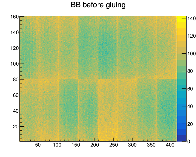
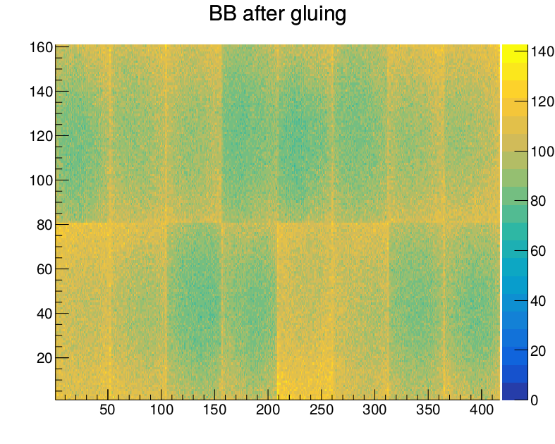
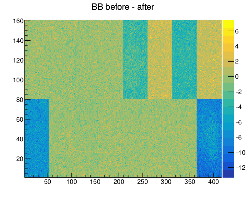
| Attached are the bump bonding threshold maps before and after cap gluing and the (before - after) difference for M1522. |
| Attachment 1: M1522_beforeGluing.png
|
|
| Attachment 2: M1522_afterGluing.png
|
|
| Attachment 3: M1522_diff.png
|
|
|
20
|
Wed Oct 2 12:41:16 2019 |
Dinko Ferencek | Module assembly | First production modules assembled |
First production modules (M1530, M1531, M1532) were built on Monday, Sep. 30 2019.
There was a problem with wire bonding of ROC5 on M1530. There is a small crater on one of the ROC pads which appears to had been created by the BareModule probe card needle.
After initial tests with pXar of the 3 modules, noticed the following:
M1530: data missing from ROCs 4 and 5 (expected based on the wire bond problem on ROC5) but otherwise looks fine
M1531: could set Vana but setvthrcompcaldel and pixelalive not showing any data
M1532: looks fine.
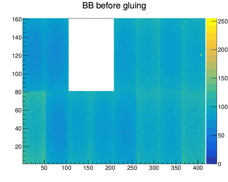
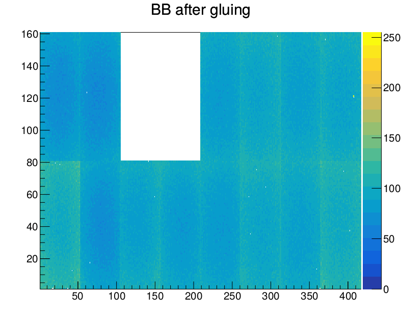
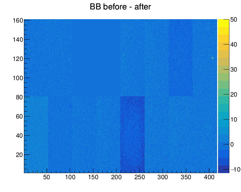
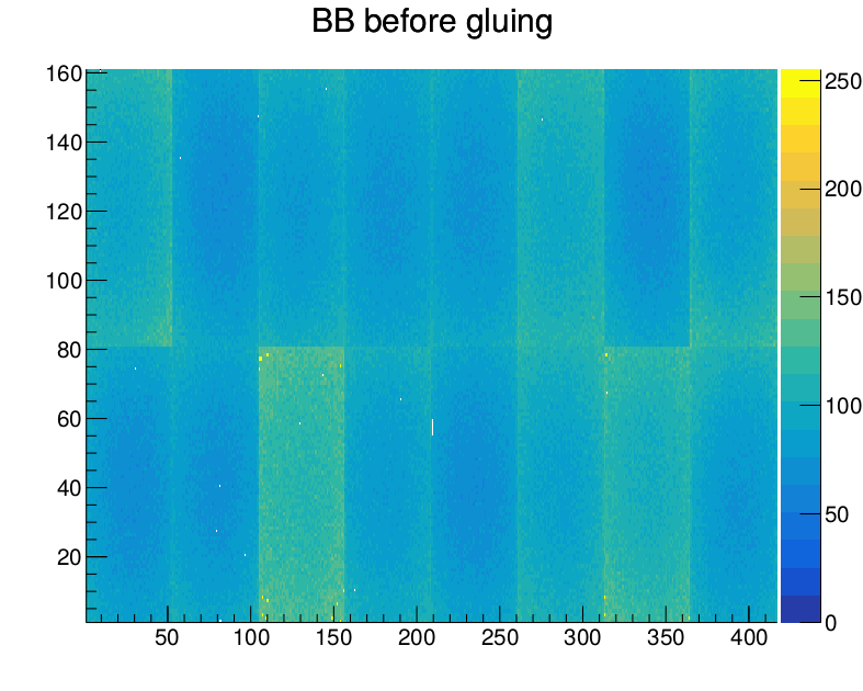
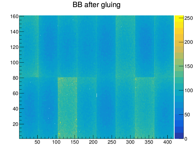
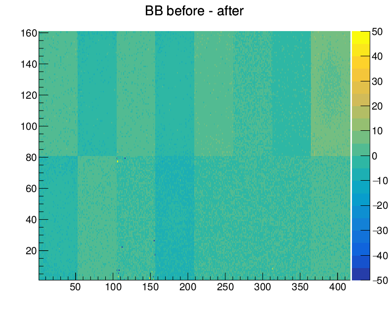
Caps were glued to M1530 and M1532 (damaged cap was glued to M1530) and Reception tests were run before and after gluing. Attached are the bump bonding threshold maps before and after cap gluing and the (before - after) difference for M1530 and M1532. |
| Attachment 1: M1530_beforeGluing.png
|
|
| Attachment 2: M1530_afterGluing.png
|
|
| Attachment 3: M1530_diff.png
|
|
| Attachment 4: M1532_beforeGluing.png
|
|
| Attachment 5: M1532_afterGluing.png
|
|
| Attachment 6: M1532_diff.png
|
|